Captainloz's Asymmetrical Re-gauging Experiment

  • Topic Is Sticky
  • 9.9K Views
  • Last Post 02 October 2021
Captainloz posted this 23 August 2020

Hi Guys,

Sorry I haven't been contributing lately. I think this video is insightful. I'm pretty happy with the way things are progressing. I took Chris's advise and went back to what I was having success with. That was good advise!

I still want to try setting up the L1 coil in series resonance.  Remember series resonance is supposed to give better voltage and parallel resonance gives better current out.  I also need to work on impedance matching.  I love the analogy of impedance matching to a torc converter. I still don't fully understand how to do this yet but that's what I'm currently studying. 

Cheers,

Loz

Order By: Standard | Newest | Votes
Chris posted this 23 August 2020

Hey Loz,

My Friend, awesome work! I am very proud to see your great success! Very nice to see! Thank You for Sharing!

All here learning, please take special note of CaptainLoz's experiment, this is very well done, very professional!

We, our Team, the support we each give each other, it is first class! We are all so lucky to have such a great bunch of people around us! You all are awesome!

Best wishes, stay safe and well My Friend,

   Chris


P.S: I have moved this important experiment out from: Nonlinear resonance to this new thread.

Jagau posted this 23 August 2020

HelloLOz

I join Chris to congratulate you LOZ, very nice demonstration.


A lot of material to study this is great.

I took the time to study it, I just got back from a great fishing weekend.

I think we have a very good team here, Chris you can be proud too.


Jagau

Captainloz posted this 24 August 2020

Thanks Guys!

To be very honest I wouldn't be this far without aboveunity.com.  This forum is the best!  And I really appreciate being a part of it!

Cheers,

Loz

Chris posted this 24 August 2020

My Friends,

I did not have a lot of time this morning and since then, have reviewed CaptainLoz's full video. Awesome Work Loz!

Loz has nailed Partnered Output Coils! He should be very proud! A huge achievement! Well Done CaptainLoz!

Disconnecting L3's Diode and seeing the Lights go almost completely out, is 100%  how this should work! A tell tail guide that the Two Output Coils are Interacting how they should.

Loz full Credit My Friend, Well done, you should be so very proud of your achievement!

If you feel, at sometime, you could drop the thread down to Tier I, for all public? Only when you are ready though!

I would like to ask all members, please support Loz's Work, Please replicate and share your results on your own dedicated thread.

Please beware, this is going to move very fast all of a sudden, soon many people will require help. I ask all members, please help others as we have here on this forum. This is the only thing I ask of you. All of Humanity needs to have this technology available to them, its super important!

If I may add, Input Circuitry like YoElMiCrO has shared with us, at the resonant Frequency, may be useful also:


Of course, L x C = T in Seconds and aiming for a pulse like this:


Congratulations Loz! 

My Friends, you all are awesome and I have huge respect for you all!

Best wishes, stay safe and well My Friends,

   Chris

Atti posted this 24 August 2020


Hi.

If there is an intention to share more, then some explanation for physical implementation would also be needed. So the winding directions which is marked in the picture. But if you want.

Atti.

Chris posted this 24 August 2020

My Friends,

Simplicity:


Loz has done an awesome job!

Remember, each Coil is an Antenna! No loop backs are needed, as Each Individual Coil, L2 and L3 oppose each other and this opposition makes for the so called Non-Inductive Component we often see in the Kapanadze Devices. The Turns Clock Wise and Counter Clock Wise are best thought of as separate Coils, this is L2 and L3 individually.

The method CaptainLoz uses has a better Coupling Coefficient and the Output will be greater as a result.


My Friends, Simplicity, keep it simple and don't let your mind over complicate this!


There is no Magic, no mystery, its just a few Antenna's, wound in a Helix, with a lot of EM Radiation at the 1/4 Wavelength! Electromagnetic Resonance.

I want to thank Loz for sharing his work, a massive success! Some are not ready to share their work, with similar successes, some have self running machines. So this is a big step forward and many here now have a new bench mark to follow.

Best wishes, stay safe and well My Friends,

   Chris


P.S: Your Video is being posted over at ou.com by member Color. I have dropped this thread down to Tier I from Tier II as its not something we can work on in private now.

Yes the skeptics are already out, we need to try to ignore them. You all are safe here! I will Ban them if they come!

Captainloz posted this 25 August 2020

Hey CD,

I use the wavelength frequency of 37.241 Mhz / 444 = 383.76 Khz (harmonic). I just picked the frequency based off of what capacitors I had on hand.  I think we just need to make sure whatever frequency we choose is a harmonice of the wavelength, of the length of the coils. 

Cheers,

Loz


Captainloz posted this 25 August 2020

Hey Chris,

It's fine for it to be on Tier1. I thought I had this video on a private link.  It's all good, let's get it out there! 

Cheers,

Loz

Captainloz posted this 25 August 2020

Hi Atti,

I started winding the coils from each end using the right hand grip rule, (current pointing into the middle).  When you get to the middle just fold the wire over and come back on itself 7 turns, then fold the wire again and wind back to the start.  So it's just 2 layers.

The torid OD is 62mm, ID is 35mm, 11mm thick.  I got these about 10 years ago and I can't find the record of the type of ferrite. I'm pretty sure I got them off Ebay.

Yellow wire is 14 AWG (L2 & L3)

Red wire is 2.5mm (L1)

General purpose diode's 6A05 - 1212

2 x 14V bulbs

1 x 12 V 7.5 wLED bulb

2 x WIMA 2kV, 2nF caps 

Cheers,

Loz

Chris posted this 25 August 2020

Hey Loz

Regarding:

Hi PM,

I'm reading the input power right from the Rigol power supply.  Why is that not an accurate way to determine the watts being consumed by the input?  That's why I purchased this power supply I was sick of figuring out my input watts.  The output is being read by the scope.  One probe is across a 0.1 ohm resistor set to 1x and 10x on the scope. Ohms Law measurement of: 1 x 0.1 x 10 = 1 Ohm. Meaning if you have 1 Volt measured across the 0.1 Ohm resistor it is 1 Amp, because 1 x 1 = 1.  The voltage is being read across the load.  If you watch the video to the end you see me put the scope on Averaging sample rate.  It still shows I'm getting more out than in.  If I'm not taking the readings correctly please advise.
Thanks,
Loz


Don't let them get at you!

I have a Rigol DP832 Precision Power Supply, same as yours. I have calibrated my scope and you know what, after my Scope Calibration, I found my DP832 to be spot on!

Don't forget, we get Rigol Certification with our Power Supply's! This is to say that Rigol knows a fair bit more than some person yelling Measurement Error from the Roof Tops!

Greater than 10 Watts on the Input, that is not Measurement Error! If we were debating 0.25 watts, then that would be a different story!

Please ignore them, they have sour grapes! They actually don't know as much as they allow others to believe, if you want an example, read through the link that was posted.

I fully support you mate! I know whats possible with these machines! They don't!

Best wishes, stay safe and well My Friend,

   Chris

Jagau posted this 25 August 2020

Hey loz

Thank you for sharing your research on the Aboveunity.com site.


As you can see, it is only here on this site that things really happen with real experiences. Contrary to the other sites which do not have anything to put under their teeth it must not be easy for them to see that here we succeed, the problem over there, there is that there is a lot of blah blah blah and not enough real experiences .


Keep it up Loz is how we develop with real things to be verified. Don't let yourself be influenced by those who can do nothing but criticize those who succeed.


As Chris has already said, we are very advanced here.

 P.S.
I see that you noticed a very important little detail that I also noted in my research, the change in load impedence brings a change to the source it's real Loz


 I'm still studying your video, very interesting and a lot of material, thank you


Jagau

Captainloz posted this 25 August 2020

Hi Guys,

Thanks for the support!  Obviously this is just the start, there is still so much more to do to get this transformer to self run.

I'm finding a high percentage of the power is being consumed in the diodes. I also tried a bridge rectifier for the output and that uses too much power. 

As nice as it is to see the measurements on the scope. It's still a long way off being a self runner.  Also, I'm still open to the possibility that I'm making a measuring error (although I don't think so).  I've asked a physicist professor friend of mine to take a look. We have discussed this before and he didn't take me seriously, but now I have something to show I'm hopping he takes a serious look.  We need this to become mainstream!  We need to show Lenz's law can be broken with Asymmetry.  I think this experiment clearly shows that.

Cheers,

Loz


Atti posted this 25 August 2020

Hey Loz!

The winding process is extremely important. We can see from the various works.
I don’t want to mention anyone in particular, as everyone’s work is important and instructive. So thanks to all the active creative people!
Measurement is important but not essential. It is important because it confirms the right path.
Such results lead to the path to a stand-alone machine.
Don't worry about who says what. Do it as you see fit.
In my opinion, everyone can learn from what is presented here if they are serious about building a machine.
I’m still studying the video and posts.

Atti.

Chris posted this 25 August 2020

Hi Guys,

Thanks for the support!  Obviously this is just the start, there is still so much more to do to get this transformer to self run.

I'm finding a high percentage of the power is being consumed in the diodes. I also tried a bridge rectifier for the output and that uses too much power. 

As nice as it is to see the measurements on the scope. It's still a long way off being a self runner.  Also, I'm still open to the possibility that I'm making a measuring error (although I don't think so).  I've asked a physicist professor friend of mine to take a look. We have discussed this before and he didn't take me seriously, but now I have something to show I'm hopping he takes a serious look.  We need this to become mainstream!  We need to show Lenz's law can be broken with Asymmetry.  I think this experiment clearly shows that.

Cheers,

Loz


Hey Loz,

There is always room for improvements! So yes, I agree!

There is always the possibility of measurement error, we all make mistakes. However, you have done nothing wrong from what I can see! I have checked your measurements and see nothing wrong! Everything is good! I cant tell if probe settings are 1x or 10x, but I saw you checked and double checked!

What is obvious when there is no other explanation, leaves only the obvious left, you are measuring excess Energy in your Machine! You have everything right! There is no Error!


It is really important that we are not so fast to pass this by!

We must trust ourselves, trust our abilities and have faith in what is possible! Let NO ONE Dismiss your work, but at the same time be open minded. As you are already!

Don't let any one tell you that you have it wrong, because, if you have it right and you dismiss it, you have wasted your years in research for nothing!

Stay Strong and stay focused My Friends!

Loz has Partnered Output Coils exactly Right, This is how they work, as Kapanadze shows, Don Smith shows and many more before us! Please everyone, get on board with this, please support Loz's Work! Please I ask you all to pass this on to those in front of us, new comers. Soon they will come in hordes!

NOTE: What we are sharing is much simpler than many of those before us! Because of Diakoptics! Some researchers in the field have been doing this for 20, 30, 40 or more years, so a bad case of Sour Grapes is going to be common! We must ignore these people that have nothing after so long in the field! They will try to destroy our achievements!

My post here, may be of help to some.

If we do not do this now, this could be Humanity's last chance!

I am so proud of you all! My Friends, You are the strength the world needs!

Best wishes, stay safe and well My Friends,

   Chris

YoElMiCrO posted this 26 August 2020

Hi all.

@Captainloz.

I have seen your video quickly, if you are interested in another opinion
I will calculate the output power applied to the bulbs,
as the waveform is complex, time must be integrated
about voltage and current, then we take the average and from there
we extract the active power applied to the load.
Regarding the power that your power source reflects,
there is no doubt about it.
Thanks for sharing your experiments, this is the forum to do it.
It's just another opinion, because the more we are, the better.

Thanks in advance.

YoElMiCrO.

Chris posted this 26 August 2020

Hey Guys,

Just a reminder, Loz gave us measurements on L2 and not from L3. L3 must also have the same Power in this Coil, because of Lenz's Law, This Coil, L3, is the Yang in the YinYang Relationship ( L2 and L3 ).


The YinYang is important to think about here, Symmetry between L2 and L3 but Asymmetry back to L1.

Thank You to all, for Supporting Loz! Thumbs Up and Favoriting this helps show your support!

Best wishes, stay safe and well My Friends,

   Chris

Maxxon posted this 26 August 2020

Hey, Loz .

You can easily verify by connecting all your load lamps directly to your power source and compare the lamps current draw with same voltages you had on your device output.

Max


thaelin posted this 26 August 2020

Hey Loz:

   Try ultra fast diodes and gang up say 4 of them to lower the voltage drop across them.  Like doing with two resistors, in parallel, they will be 1/2 the value.

thay


Captainloz posted this 26 August 2020

Hi Guys,

I was playing around last night by upping the voltage to 65 volts and I've done some damage. I've blown out my mosfet(s) and it looks like diodes as well. 

Max, that's a great point I will do that. Although I don't think that will not show the power loss in the diodes.  They get very hot so are drawing a lot of power which is shown across the resister, if I connect the DC power supply directly to the load I won't see the power consumption of the diodes, which is real power being generated by the coils but not being consumed in the load. That's why I think I'll need to get the output up to over 3 x before it will self run.

Thay, good point! That's may help with what I just said above to Max. Thanks!

YoElMiCrO, I'm not sure I understand but I'm planning on using the Math function on the scope. Itsu sent me this video link 

which I watched last night but still need to try.  As soon as I get the circuit back up and running I will try this.

I will say to everyone that in all the years I've been doing this, I have been measuring input and output basically the same way (maybe incorrectly) and this is the first time I've been able to measure over 20 watts extra out. So even if I'm making a measuring error it's still the best experiment I've ever done.  Obviously I'd like to see a lot more power out, but this is where I'm at. I encourage you to replicate this and see if you get the same results. 

I know I not the smartest guys on this forum so if I can do it you can do it.  As Chris says "keep it simple"!

I need to keep it simple because I'm just not smart enough to make it complicated. Hahaha!

Lastly, I find it really hard to make time for this forum so if I go quiet for awhile it's just because of life responsibilities. But I'll do my best to keep contributing as much as possible.    

Cheers Boys!

Loz


Augenblick posted this 26 August 2020

Max,

Great current test:  bypass the circuit entirely for an A-B test.

A = load only.

B = circuit and load.

Thaelin,

Series diodes increase the forward voltage drop, reduces current, and they share a slightly reduced thermal load.

Parallel diodes 'ideally' divide the current, share the thermal load, but the semiconductor threshold aspect of each remains. The forward voltage drop stays roughly the same no matter how many diodes are paralleled. That's ideally ...

Mismatched parallel diodes can cause problems, such as thermal runaway and avalanche.

https://www.quora.com/Can-we-put-two-diodes-in-parallel-in-order-to-have-double-current-carrying-capacity

https://www.eevblog.com/forum/beginners/diodes-in-parallel/

Hope this helps.

Cap,

Very encouraging results! Thank you!

-A-

Chris posted this 26 August 2020

My Friends,

Again, Loz's Measurements are Ok! There is nothing wrong, its a very close approximation of whats going on.

Soon we will see people saying things like: "I have been doing this for years", "this is my idea", "I was first to do this", "your'e doing what I did 20 years ago" and so on...

We must be vigilant and diligent in how we progress! Let no one steer us! Stay on track! It wont hurt to hold a few things back, little secrets, let others progress, but make sure they are learning what they are doing, and not being told what to do!

Many other people do not like to give credit where Credit is due, so beware, others will try to steel your hard earned Spot Light!

We know, we are World Leaders in this technology!

So be proud! No one else in the Western World has been able to get this far!


We at aboveunity.com are the leaders! No one else! We have pioneered and brought forth the Technology you are seeing right here!

  • It works! It is simple!
  • It is Cheap!
  • It only takes some understanding!


You will Note:

Ref: PM Criticism

Partzman points to Measurement Protocols I have bought forth as a reference! Measurement Protocols Here: Partnered Output Coils Measurement Protocols, See our Measurements Section for some further reading.

Please read the entire sections if you wish! You will note, there are a lot of people, experts in the field, still have no idea what so ever how to properly measure these machines! They still think RMS on the Input is OK To Use! They are so wrong! I will point out, some trained Metrologists make this mistake! We are farther beyond their Skill Set! So do not fear!

Loz questioned Partzman and got no answer:


Loz, your'e a humble and genuine bloke and should have had a response! No answer gives us an answer in its own right!

Our Measurement Protocols are some of the best in the world! Why? Because we have Training on how to properly measure these Machines under working conditions! No one else does!

If people do not pick this up and replicate, then this may be our very last chance! It all depends on you My Friends, and those that follow!

Best wishes, stay safe and well My Friends,

   Chris

Captainloz posted this 26 August 2020

Hey Chris,

If people watch your videos its all in there.  My experiment is proof of that.  I was feeling very frustrated for a long time but then I stumbled on to your youtube channel and it inspired me to keep going.  I actually have your book from way back, I wish now just stayed with it but I went down the Ruslan and Akula rabbit holes for too long without understand Asymmetry and the re-gauging process.  Anyway mate I'm just trying to say you should be proud of yourself. You are doing a great thing here!

Cheers,

Loz

Chris posted this 26 August 2020

Hey Chris,

If people watch your videos its all in there.  My experiment is proof of that.  I was feeling very frustrated for a long time but then I stumbled on to your youtube channel and it inspired me to keep going.  I actually have your book from way back, I wish now just stayed with it but I went down the Ruslan and Akula rabbit holes for too long without understand Asymmetry and the re-gauging process.  Anyway mate I'm just trying to say you should be proud of yourself. You are doing a great thing here!

Cheers,

Loz


@Loz, Thank You My Friend! I appreciate your Post! I cant do it without all of you, you are the real Legends!

@All, I have drawn Loz's circuit from the video:


@Loz, if you can point out any mistakes, only when you get time, no stress right now. Just when you get time!

This is for others to follow, but remember, your Coils may require different capacitors, so please be aware of this when replicating. Base your replication from what Your Coils need to see! Many posts, and Loz's Video explains this!


The Bedini Crew, would be pretty sad after sticking with him for so long and having nothing at the end! We are completely independent, and we have succeeded well beyond their wildest expectations! With no BS, its all right in front of all readers! It is simple, no Magic, nothing special required, all that stuff is all BS!


All anyone needs is a few simple Coils and the right knowledge! Obtainable only here! Steven Mark told us this:

Very, very cheaply put together, there is no mass circuitry involved with any of this stuff, its just the knowledge of the coils and how they interact with each other.


Loz, you should be super proud of your self old mate! wink

Best wishes, stay safe and well My Friends,

   Chris

Captainloz posted this 27 August 2020

Hey Chris,

Yes circuit looks good!  

Cheers,

Loz

Atti posted this 27 August 2020

Hi.

 @All, I have drawn Loz's circuit from the video..........  Hey Chris, Yes circuit looks good!  

I may be in trouble. I ask a lot. But if I understand correctly this is not a simple L2 and L3 coil. For clarification:
If this is the case then the L2 and L3 coils (one by one) are arranged in the same way as Fighter’s work. And that's how it's all different.


Atti.

Chris posted this 27 August 2020

Hey Atti,

Wind the Coils, measure the length, calculate as Loz has and then do the experiment.

Drawn out procrastination is only going to confuse you and everyone else, when there is no need!

Loz said: Keep it Simple!

I have said this also:


If you have been reading, and studding, then you will know only three Coils are needed:


There is no complication, don't make this complicated when there is no need for complication!

Best wishes, stay safe and well My Friend,

   Chris

  • Liked by
  • Augenblick
YoElMiCrO posted this 27 August 2020

Hi all.

@Captainloz.

If you want try this.

In this way, do not open any type of doubts regarding
to the power at the load, since the capacitor will store
all the energies that circulate through your secondary.

I hope it helps.

YoElMiCrO.

raivope posted this 27 August 2020

Hi,

Just a few hints for the circuit.

Primary coil has C1 for resonance. It will work, but discharging C2 into C1 directly thru the switch is sometimes costly when voltages are different (unless resonance). Trick is to have bifilar primary where you have LC on second primary without other connections. If you do not have h-bridge to drive the primary, you need to protect the single mosfet switch and this LC idea to tap the CEMF is good - having LC on bifilar will clip the non-wanted peaks of the same parallel coil. (but anyway - this primary thing is not a big problem)

Hint2: you are using second primary + diode + shunt for analysis, but in a future you should short this coil without any diode, because diode dissipates energy. Ideal is to have superconductor coil + ideal shorting - thus no dissipation. Trick is that you can have two low ohm (rds-on) opposing MOSFETs sourced together and switched both at the same time. You can keep the diode, but add the shorting-bridge in parallel to it.
Plz refer to my pdf in July 26th: http://www.aboveunity.com/thread/raivope-s-isolated-switching-circuit/?order=all#comment-3e5196a4-d0d8-4ec0-8de4-ac040132371b
Page 15-16 (shorting-bridge).

Captainloz posted this 27 August 2020

Hi YoElMiCrO,

Thank you for the power measurement circuit.  I will give it a try. 

Hi Ralvope,  

Some great advise there, also thanks for the switching circuit pdf. I think I could get much better results with this experiment if I was using a full bridge, I'd like to set up the L1 coil in series resonance.  So many things to try with this set up!

And Guys,

Just a quick point on this set up.The 2nf C3 cap is not needed to see the affect, It only adds a little to the overall output.

And just to be clear with one of the notes on my note pad.  Where I have L1, L2, L3 written down.  I have (red) next to L3 that is just referring to red magic marker I marked on the L3 yellow wire.  

Cheers,

Loz

Chris posted this 27 August 2020

My Friends,

In the thread: The Input Coil, I posted about the Input Coils importance.

I don't want to be picky, Loz has done an awesome job, and most definitely don't want to confuse anyone, so some might be best to not read all this Post perhaps. I only aim to help!

The Input Coil has an optimum length and therefore operation frequency: One Quarter the Wavelength or close to the Partnered Output Coil Operating Frequency. The Input Coil is directly related to the Partnered Output Coils, frequency wise, thus length wise.

This means, the Input Coil's length is the same as one Partnered Output Coil / 4, approximately.

Loz already pointed this out in the video.

Optimising the Input Coil Length and operation will maximise the over all efficiency and make the Input go right down, even go Negative.

You all are awesome and you all should be so proud of yourselves! Humanity has never had an opportunity like this ever before!

Best wishes, stay safe and well My Friends,

   Chris

Captainloz posted this 30 August 2020

Hi Itsu

Thanks for your video. Here is the reply-  

I still can't seem to find where the M (mean) data is displayed on my scope.  However as you can see if we take the average amperage reading my efficiency drops drastically, however I'm still showing a small gain.  Note; I do have my circuit set up a little differently than the last experiment, but it's basically the same.

Cheers,

Loz

Chris posted this 30 August 2020

Hey Loz,

Have confidence in measurements!

I have posted a Post to the Measurements Thread to help you out with taking measurements. The protocols are right so please be confident!

The video:


Please go and read the post, there is more there!

Keep Input and Output Measurements separate, state them as such: Input or Output Measurements.

Keep your Chin up My Friend, your'e doing fine! If you follow the protocols I have posted for you, you wont go wrong!

Best wishes, stay safe and well My Friend,

   Chris

Captainloz posted this 30 August 2020

So sorry Guys!

Not above unity! Bad probe and measurements! It was not my intention to mislead anyone. Obviously I'm frustrated and a little embarrassed, however I'm glad you guys pushed me for the proper measurements because it's been a great lesson. Chris and Itsu thank you for helping me find the error. I've learnt a lot about my scope but more importantly to check your probes for accuracy.  

I've been using that same probe for ages so all my previous results have to be incorrect.  Chris so sorry for putting you and everyone through this.  I feel terrible about this but I've learnt my lesson. Can you please take my devices off the greater than COP1 list.

Cheers,

Loz

Chris posted this 31 August 2020

Hey Loz,

Mate I appreciate your Honesty! Honesty always trumps BS!

Many of us have seen the same effects you have shown, and many of us are doing great work! Some of us even having self running machines, where no measurement error can occur and these sorts of problems are irrelevant. 

I very much appreciate your Honesty and finding the problem is a great lesson for the basic Oscilloscope use, errors can easily be made! In the past, many times I have had readings I have had showing Above Unity Results, in the early days, Errors were found. Finding them is sometimes part of the journey!

As is not finding them!

The skeptics will be having a field day right now, but that's fine, being honest is more important! I value Honesty very highly!

Best wishes, stay safe and well My Friend,

   Chris

Jagau posted this 31 August 2020

Hello Loz
I have a little trouble understanding your second measurement.
In the first, the probe is at X10 and the Ch4 is at 100A.
In your second measurement you leave ch4 at 1X and you lower the ch4 from 100A to 50A and 2A without doing an autoset?
If you did the math ( ch3 X ch4 ) were you correct in the first measure 

DoI misread what you are showing me?
help me understand

Jagau

Augenblick posted this 31 August 2020

Cap,

I'm sure all members back your experimenting here, gains and losses. These are very important steps in learning and progress. An occasional slap on our forehead works wonders. I've had an associate toast a $10,000 exotic/rare component, from a simple wire crossing. It set us back some weeks. We just slapped our heads and moved forward. The results were rewarding after all.

You're so close. Finish to win!

Best,

-A-

Chris posted this 31 August 2020

@Loz,

The Guys are right, measurements in the last video are not as accurate as before. You need all waveform data in screen:


That's why you are not getting RMS Readings. I would really like to see a good Screenshot, one of input and One of Output, but I trust if you want to call measurement error, its ok! I understand why you would go down this path.

I have not seen a Scope Probe read: 7.57 A then drop to 579 mA, just by swapping the Scope Probe, that's a massive variance! Some very bad Scope Probe Damage there! 


Just so you know, there is a lot more than 579 mA in that Circuit! Powering those Globes:


579 mA does not fit right for me! Still, if your Scope Probe was that badly damaged, it is possible.


My Friend, I get it if you want all this to go away, if all the negative attention is getting to much, say the word. It is very easy for us to move this back to Tier II and hide it all from the Skeptics! Its not hard!

Jagau has good advice, resetting the Scope is best done to get the right probe Measurement.

You need to make all your Videos: UnListed if you want to!

Again, I value Honesty very highly!

I very much despise Mis-Truths and Non-Sense, the approach of the skeptics we see all the time!

Best wishes, stay safe and well My Friend,

   Chris


Chris posted this 31 August 2020

Hey Loz,

Sometime back I posted a video of how to calibrate the Rigol Oscilloscope:

Before Scope Calibration:


After Scope Calibration:


Test and Check your probes with a DC Power Supply. Of course bad equipment needs to be found and resolved.

Best wishes, stay safe and well My Friend,

   Chris

Chris posted this 31 August 2020

My Friends,

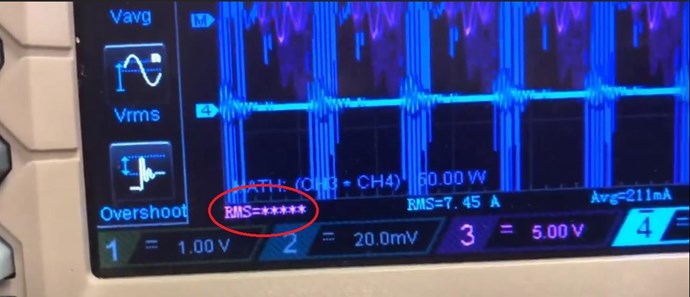
First of all I want to thank Captainloz for his honesty and coming forward with a Bad Probe.

Second, I want to reiterate my above post, Please verify your Scope and Probes, verify by doing simple calibrations on a regular basis to check equipment. Normally you will be fine, everything will just work and it will be pretty accurate!

Third, I want to say, what Loz has shared here does work! Just because we have seen a Bad Probe, should not discourage us! Especially those learning, the up coming!

Why?

Because many of us have very advanced machines running, based on the exact same technology, some of us have Self Running Machines, here is our Public and Tier II list:


Personally I am a little cut, but I knew deep down, this was on the cards. We all make mistakes, it is inevitable, we are not perfect. We must remember, this is just a crack in the road and we must keep focused and solid in our path forward.

@Loz, My Friend, Please do not worry! This sort of thing happens! Now you know how the scope works and how to calibrate and test the Scope and the Scope Probes. We fully support You Mate, like Augenblick said, no matter what! You are truly on the right track! Please I ask you don't give up! This will work with the right fiddling, you have my word!

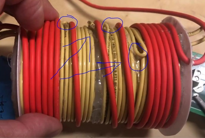
The best way to think of this is the same as the BTG, or Kapanadze's Grenade Coil:

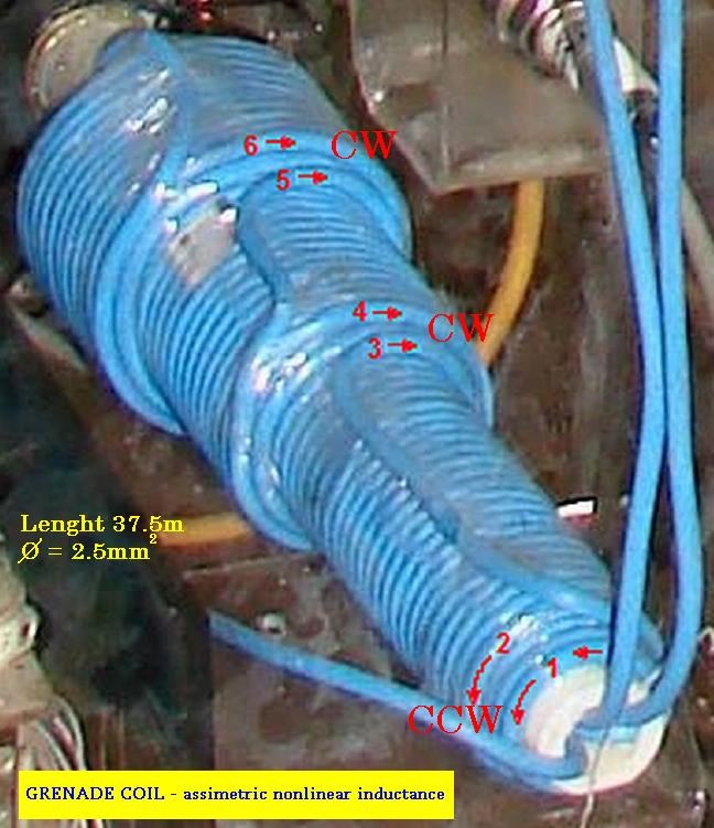
Well, Turns Clock Wise and Turns Counter Clock Wise, the exact same basic operation is the same! We must have Magnetic Resonance, which you are 100% spot on and the Voltage must be Increased sufficiently, remember: I = V / R

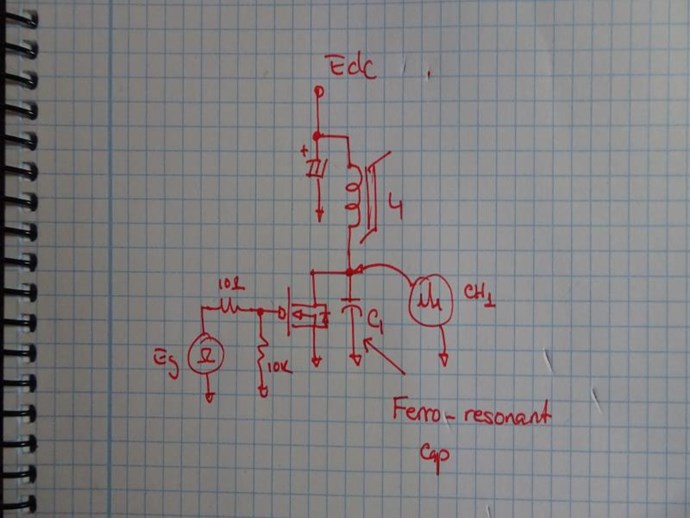
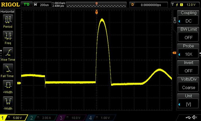
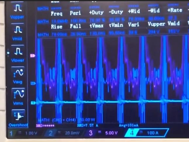
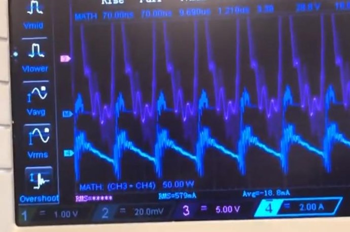
You saw the Voltage and Current increase under load, this is how it works, to a point. Increase your Load!

It is easy for the Skeptics to have a field day from this sort of thing. But as I said, sooner or later it was inevitable, something would go wrong, but that's life! We have to Motor On!

Evolution is not for the faint hearted! We must push forward to succeed! How many rockets did SpaceX loose before getting to Space?

@Loz, get your scope back on track, throw out Bad Probes, do regular Scope tests and Calibrations, and we will get you back on track! Avoid all High Voltage Testing on the Scope, High Voltage can damage Probes and the Scope!

Best wishes, stay safe and well My Friends,

   Chris

Captainloz posted this 31 August 2020

Hi Chris,

Thanks for those wise words!

After further calibrating of my all probes I've detriment that the probe I thought was good (the one in the video) is also bad! I haven't had time to re-test everything yet. If I'm not over unity, I'm very close! You know, I think part of the problem is I also find my own results hard to believe so I'm very open to the idea I've made a mistake somewhere.  And that has made me too quick to dismiss my own results. With that said even though I have found serious problems, that doesn't mean this experiment is a bust. 

The last video was just to show the bad probe and the huge difference between the two (even though both those probe were bad!). I don't think I had all the Math settings set up correctly in that video. 

Chris my scope is a little bit different than yours in showing the Math data. I expect the Math data to be displayed with a W but it's showing V.  Even though I have the values set correctly on the probes. Math is AxB.  Measure, Source is on Math, but this keeps jumping to a CH this display doesn't have the little check boxes.  And All Measure Source- is set on Math this does have the check boxes like yours but this is just sets up what you see on the display.  I need to find and download the manual to see why I'm not showing Watts next to the math data.

Anyway, I will be a lot more carful now in posting results.  I've learnt a lot from this experience. 

Jagau,  I want to carefully set everything up before taking a screenshoot of all the data for your review.

-A-, thanks for your support. Talk about a slap in the head. I was feeling very defeated but after I found the 2nd bad probe I'm more focused than ever. 

Cheers,

Loz 


Jagau posted this 31 August 2020

Hello Loz
Don't worry my friend, I learned a lot myself with your thgread, I thank you. At least you have tried it, discouragement is easy but I believe that by working together we can succeed.

I would have another video by the same author as another one proposed to you, this one is very very interesting too
good reading


P.S. In this video you will understand that sometimes you will have to increase the value of the sensing resistor to get a reading on your oscilloscope.


Jagau

Chris posted this 31 August 2020

Hey Loz,

The Oscilloscope is a steep learning curve. I was lucky, a very good friend, whom I miss dearly, taught me everything I have been fortunate enough to learn on the Scope about 10-12 years ago now. Oscilloscope's are all a bit different, but have the same basic ideas.

The Math showing Watts issue, could be a few things:

  • On your scope, you may have to Set Watts as the units?
  • SourceA might not be set correctly.
  • SourceB might not be set correctly.
  • Make sure A x B is set correctly.
  • Make sure each Probe Channel is working correctly.
  • Make sure your Wave Triggering is set Correctly. Jagau pointed out Auto for this.


Reset all Default settings and start again from scratch is sometimes the best way to move forward.

Best wishes, stay safe and well My Friends,

   Chris

Augenblick posted this 01 September 2020

Cap,

Ironically, two new Tektronix probes arrived from Seattle a few days ago. Mine were very outdated/abused, as is the CRT scope.

So I decided to buy a RIGOL DS1054Z  today: $349 USD, no tax, free shipping, with 5 yr warranty ... hard to pass by. ... too blind to read the data, but the colors are really awesome, right?

So *all* your efforts do ripple out to our benefit.

Chris, you're a great coach, tech, and lab instructor!

Be vigilant, to be safe.

-A-

Chris posted this 01 September 2020

Thanks Augenblick, I aim to help where I can.

I hope all here will correct me, point out any mistakes I make, or improvements on the procedures I have tried to provide?

Others here are very much more advanced than me!

I think it is very important we get everything 100% Spot on, error is my least favorite friend, I aim to be correct and accurate at all times, even though sometimes this is open to interpretation.

A simple DC Test on your scope is a very good practice, you then know, your scope and Power Supply are Accurate, bench marking never hurts.

Also, this good practice, getting in the habit of taking Accurate Measurements, it gives Direction and Confidence!

Best wishes, stay safe and well My Friends,

   Chris

Vidura posted this 01 September 2020

Hey Loz, Just wanted you to know that I have made mistakes with measurements some time ago. It is certainly a bit frustrating if we believe that we made it, and suddenly the bubble bursts when we realize that something was wrong. But keep up your great effort, be confident that it is possible, there are several Devices that are showing AU and they can be made self sustaining. Personally I have become a bit more cautious after my measurements mistake, and try to always double check with different methods when I got promising results. I found it very useful to put some analogue meters, which proved to be less sensitive to interference and quite reliable . The Scope is an amazing instrument, but I found in some special cases no explanation for the response of the screen. I wish you all the best, be confident, we will be successful. Vidura.

Captainloz posted this 01 September 2020

Hi Guys,

I really appreciate all the support and advice.  And thanks for your understanding. I'm so happy everyone here is actually helping and not criticising.  I will post new results as soon as I can. 

Cheers,

Loz

Chris posted this 03 September 2020

My Friends,

Only a few more steps here and this could prove to be very beneficial!

A measurement error just before the Precipice of Success, like I said, Input Coil adjustment to get 1/4 Wave, is a dire blow to Success! A dire discouragement on the Precipice of Success!

Success comes after Understanding and Hard Work:


I do hope we all take this work serious, and do not allow measurement error discourage progress.

Best wishes, stay safe and well My Friends,

   Chris

Chris posted this 04 September 2020

Hey CD,

Be careful not to confuse Acoustic Waves and Electromagnetic Waves. We are viewing very different things in some instances.

Ref: Nothing is something by Floyd Sparky Sweet PHD


Floyd Sweet talks about both types of Standing Waves, Electric and Magnetic by changing the way the System is configured.

The Speed of Light ( c ) is still present, but because a Standing Wave has C + -C = 0, same is true of H, H + -H = 0. I believe the next bit is a typo.

Thank You for posting this, it is worth seeing the difference here!

Best wishes, stay safe and well My Friends,

   Chris

Captainloz posted this 13 September 2020

Hi Guys,

I guess some of this thread can be a used as a good example of how easy it is to make measurement mistakes. Haha! Hopefully people will learn from my mistakes!

Here is a quick video showing results with my new scope. My old scope is damaged and won't display the Math data correctly.  I don't think the circuit is above unity. I think I've damaged all my .01ohm resistor blocks because I pumped too much current through them.  The real test will be when I get my new 50 watt wire wound 1 ohm resistors to try in the circuit.  I'll will post results once they arrive.

Cheers,

Loz

Jagau posted this 13 September 2020

I will follow your new data with interest.
Don't worry as you say so well we've all learned. So we keep learning
Cheer LOZ


Jagau

We're Light Years Ahead!
Members Online:

No one online at the moment


What is a Scalar:

In physics, scalars are physical quantities that are unaffected by changes to a vector space basis. Scalars are often accompanied by units of measurement, as in "10 cm". Examples of scalar quantities are mass, distance, charge, volume, time, speed, and the magnitude of physical vectors in general.

You need to forget the Non-Sense that some spout with out knowing the actual Definition of the word Scalar! Some people talk absolute Bull Sh*t!

The pressure P in the formula P = pgh, pgh is a scalar that tells you the amount of this squashing force per unit area in a fluid.

A Scalar, having both direction and magnitude, can be anything! The Magnetic Field, a Charge moving, yet some Numb Nuts think it means Magic Science!

Message from God:

Hello my children. This is Yahweh, the one true Lord. You have found creation's secret. Now share it peacefully with the world.

Ref: Message from God written inside the Human Genome

God be in my head, and in my thinking.

God be in my eyes, and in my looking.

God be in my mouth, and in my speaking.

Oh, God be in my heart, and in my understanding.

Your Support:

More than anything else, your contributions to this forum are most important! We are trying to actively get all visitors involved, but we do only have a few main contributors, which are very much appreciated! If you would like to see more pages with more detailed experiments and answers, perhaps a contribution of another type maybe possible:

PayPal De-Platformed me!

They REFUSE to tell me why!

We now use Wise!

Donate
Use E-Mail: Chris at aboveunity.com

The content I am sharing is not only unique, but is changing the world as we know it! Please Support Us!

Thank You So Much!

Weeks High Earners:
The great Nikola Tesla:

Ere many generations pass, our machinery will be driven by a power obtainable at any point of the universe. This idea is not novel. Men have been led to it long ago by instinct or reason. It has been expressed in many ways, and in many places, in the history of old and new. We find it in the delightful myth of Antheus, who drives power from the earth; we find it among the subtle speculations of one of your splendid mathematicians, and in many hints and statements of thinkers of the present time. Throughout space there is energy. Is this energy static or kinetic? If static, our hopes are in vain; if kinetic - and this we know it is for certain - then it is a mere question of time when men will succeed in attaching their machinery to the very wheelwork of nature.

Experiments With Alternate Currents Of High Potential And High Frequency (February 1892).

Close