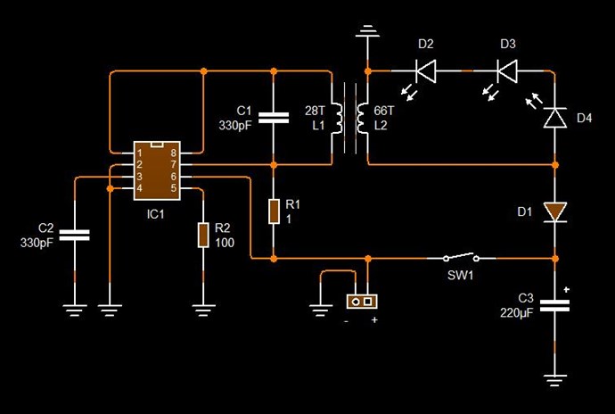
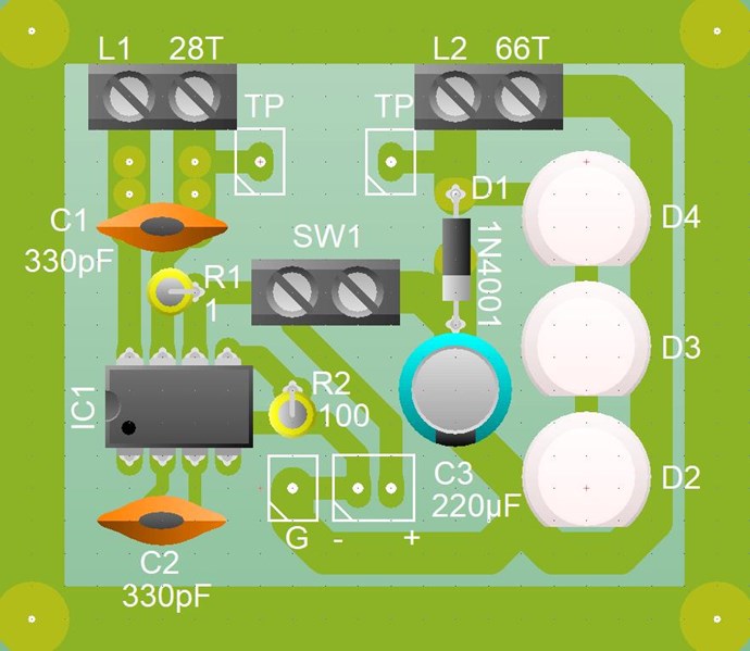
Akula's circuits- is this the principle?

  • 10K Views
  • Last Post 19 November 2020
Vidura posted this 03 September 2018

Hello Team, after watching one of Akulas videos several times(Trance and Resonance) I think to understand a little bit better the principals of operation, and so I will share this observations here, hopefully adding up some useful information. Specially this circuit which is quite simple seems to be good to grasp the principle how it works, and also is cheap and quickly for built, in order to try to replicate.

Edit: viewing the valuable information about andrey melnichenkow that Chris has posted it becomes obvious that the credits for this discovering and buildings are corresponding to him ,and not to Akula, who evidently has merely copied Andrey's work.

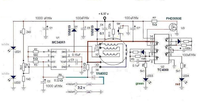
This is the schematic he is explaining on the video, I'll post the relevant details: the test points are highlighted in the colour of the scope traces.

He seems to point out that the CD4069  inverter is not needed, or not important for the basic operation, at least the shaded area, the inverter connected to the external FET forms a synchronous rectifier I would guess and could be probably replaced by a shottky rectifier if the CD4069 is not employed . The resonant oscillations are driven by the MC34063 chip, which  is an analogue dc-dc converter driver. Here the internal circuit from the datasheet:

Now this reveals a very important aspect of the operation principle: note that the fundamental frequency of resonance is 269Hz (the low value indicates that the coils are bucking), but the switching frequency of the converter is set to a much higher value by the timing capacitor C  on pin 3(for 300pF it is approximately 25uS  Ton and 10uS Toff). The Inverting Comparator input on pin 5 will shut down the switching when a the threshold voltage on the output is reached. So when the output voltage downscaled by the resistor divider  on pin 5 becomes greater than the 1.25V internal reference, the driver shuts down. With this technique it can be achieved by adjusting the variable resistor , that the switching occurs predominantly at the lower halfwave of the cycle(in the case of the boost converter, where the pulses at the yellow highlighted test point are negative), which will maintain the fundamental resonant oscillation with a minimal expense of energy.

Another detail that has called my attention are the copper sheets inside of the bobbin, which are found on some other devices of Akula as well. I don't think that this is a emf shielding, more likely it forms a capacitance or capacitor in conjunction with the second sheet at the inner end of the second winding. This will of course have no effect at the fundamental oscillation of the coils at 270Hz, but referring to the switching period of the driver with a 35uS period it will have a mayor effect, and might be used in this design to achieve a capacitive coupling of the second coil.

Note that in the following screenshot the schematic sheet which is below the circuit in the video has two modifications marked:

First a resistor in series with the output Led's -likely a impedance correction

Second the variable resistor for the shut down signal is changed  to a diferent configuration - for a broader range of adjustment


I think that this particular circuit would be a good start point to experiment as the basic design is quite simple. And in my opinion first the coil set have to be tuned to the fundamental resonance frequency, which is the tricky part, then the adjustment of the driver pulses and load impedance should be easier.

Order By: Standard | Newest | Votes
Chris posted this 12 October 2018

My Friends,

A Simpler Circuit:


I have all the files, will post in the next hr or so. Have to pop out soon:

   Chris


Light Up the Darkness!

Jlezana posted this 21 October 2019

Hello Friends ... thanks for sharing this forum, I am from Chile and I write in Spanish, I use google translator, to send you my notes.

Years ago I built the Akula circuit, and I had no promising results ... today I have trouble analyzing it again ... I have manufactured several transformers and adjusted the frequency, but it does not work more than 2 seconds with a 1000uF capacitor at the entrance, I have some equipment to measure, so now with your information I could go more calmly understanding this device ..

The current consumption of this circuit is around 4000 MicroAmperes, which is quite high.
I don't know if someone has measured the consumption current of their replicas?

In parallel, I made a very similar but simpler device that I would like to share with you and I think it works in the same way as the akula circuit.

I leave the sample video:

Thank you for sharing all this information that is really helpful in this device.
If you think this device requires a new forum, just let me know and I create a new post with the details of it.


Atte.
Jorge Lezana

Mitza84 posted this 22 October 2019

Thanks Vidura any theory is recived well i hope we see the end of this device . when i made the device i take steps first i make the oscillator part and then after is working ok i made the returning side of the device what i notice at this device is when i connect the second part with some coil  the frequency is geting higher   oscilloscope on pin 1 and the ground . because without the second part the device go on very low frecuency because of the 0.15uF (150nF)  somewhere in hundreds of hertz . (  Capacitor wich give the frequency of the oscillator on pin 3 of the mc34063,)  So just the oscilator side leds light frequency low and consumption about 10-15mA  , with the returning side leds go off and frequency higher. and amp draw  go crazy .

Mitza

Chris posted this 21 January 2019

My Friends,

The above videos were Akula's reason to make the video:


and, he then continued onto:


If I may point out:

  • The MC34063 IC is a DC to DC Converter Chip.
  • The On time is very short, in the region of 1% or less Duty Cycle.
  • The Two Coils have Inductive Interactions at every point in the Cycle.
  • Each Coil has On-Time and Off-Time. Both interacting with each other.
  • This device was originally shown by Andrey Melnichenko.


Electrical Energy is "Generated" during the Cycle. Voltage in this case must be sufficient to charge Capacitors: C2 and C5 so the positive terminal Voltage is at or just above the starting voltage. That's why L2 must have more turns, a Higher Voltage, a greater Inductance:


For example, 10 volts across the two Capacitors, C5 and C2 above, Divides the Voltage:


So L2 must have greater turns on it by a Factor. This depends on the Capacitance also, see above link for more information! So we see, Electrical Energy is "Generated" and this generation is a result of the Interactions between two Coils in Time.

   Chris 

Mitza84 posted this 19 October 2019

Hello my name is Michael but you can call me as my nickname here also i want to share something with you ,ive been working at this flashlight for over 4 months with oscilloscopes and very fine amp meters , i am a bit disapointed lately i spoke with Vadik Guk aka Delamorto about the operation of the circuit , from my perspective il belive is not a fake but,  he told me is very unstable and very hard to tune it he told me the maximum time of operation was about 20 min without power suplly i will post a pdf with conversation from him and Avalon on a forum that might be of help for some people he told me to dont waste my time because is very hard to make it work and very unstable but i cannot stop i want to see it work is like an obssesion , i hope with your help me so we get to se a working device soon guys .  i hope that my pdf will help you to get you easier to understand how is working hes name is semenihin aka delamorto .

Mitza

Attached Files

Chris posted this 19 October 2019

Hi Mitza,

Welcome! Thanks for participating! I did a replication:


Yes it is true, one can spend many hours replicating these machines. Patience and study will see success. Stick at it.

   Chris

Mitza84 posted this 19 October 2019

Hi Chris thank you for  wellcomeing me  i followed your work for a long time but i did not get my toughts online  before i make a working replication i saw also cd-sharp and vidura and the others that post good work ,i think you Chris put very precious information and i want to come with a little help to make one good replication that works , but till now i did not succed i was checking also russian forums for infos and try to get in touch with the russian guys and i spoke with Ruslan Kulabuhov and Vadik Guk ,Ruslan was a little secretous he gave me the impression that he want to help but he did not say to much he tell me even if i have a good schematic i will not be able to tune it right so is usless for me to try ,he sad that is an atomic process happening in the core and the ferrite will shatter eventualy , so will get destroid from vibration after a while so is not forever , Vadik guk try to put me on a good track ,he sad not to louse my time with this lantern cose will be very dificult to make it work and to try to work with the katcher and grounding because he had very good results with these  he gave a a forum where they put updates if you are interested to know i will post the link because i do not want to get baned for promoting other forums . 


Mitza

Mitza84 posted this 19 October 2019

i saw your replication what was your consumtion do you remember ? i used one led exacly like vadik use in the 4 videos that you posted before , and i get very good brightness under 5 mA  but the problem is to make it self sustain thats my goul . the think is when i ad the other part of the circuit with the cd4069 and the transistor ( the return of energy ) the circuit it start to take much more energy and here i got stuck.

Mitza

Chris posted this 19 October 2019

Hey Mitza84,

You wont get banned for posting a single link. wink

I had that machine, after many hours of tuning and fiddling, running for several minutes at a time with no input. I cant remember the consumption, but the capacitors held the machine in self sustaining mode for quite sometime.

Some advice if I may? Be patient, learn as much as you can, build, experiment, document your work, and share with us as much as you can - We will do the same!

Together, we can all progress!

Everyone is safe here!

   Chris

Jlezana posted this 22 October 2019

Thank you very much friends for the welcome, give me a little time and I will create a separate thread ... with the details, have a little patience, I will try to do it in English Translated so that you understand it.

I want them to be able to replicate it and share experiences about it.

Effectively work with the lasersaber scheme, the problem is that he does not give details of where this circuit comes from, it is difficult to adjust and does not always work ... and worse still, when it does, it consumes a lot of current, about 3 or 5 milliamper . My replica is working in only 60uA.

I will give you more information on where the base scheme comes from, and more practical and technical details that I hope will help you in your replicas.

I do not want to dirty this thread with this project, because I have also assembled the Akula circuit and I have several doubts that I would like to help me understand.

My first help I need is:
Will someone be able to switch to text in English, the photos posted by the Admin (Chris posted this 04 September 2018 - Last edited 04 September 2018)
So I could translate and read them in my language and try to understand more.

I appreciate the help.


While I will be writing a little bit the New Thread I will call: Modified Armstrong Oscillator (OSC_ARM_MOD_JL01)

Regards
J.Lezana

Jlezana posted this 22 October 2019

Thanks Friends ... the New Thread is over here:

http://www.aboveunity.com/thread/modified-armstrong-oscillator-por-jorge-lezana/

I hope you like it and serve your experiments.


Regards
J.Lezana


Chris posted this 22 October 2019

I hope that Chris will not bann me for posting to much theorylaughing.


No, absolutely no way that I would do that Vidura.

I only Ban Trouble makers, Trolls, those that are here to distract, attack, to be-little others, you're not going to get Banned for trying to understand the Technology.

I value everyone here, and I consider you all part of my family, extended family. Like I have said, we are all here making History!

Best Wishes

   Chris

raivope posted this 23 October 2019

Hi all!

Interesting topic!

To my knowledge - there are many different working principles, better to differentiate:

  1. high frequency, fast switching, CEMF (cold) pulses, which do work in battery (or capacitor). They cannot be looped directly. (Bedini, Don Smith, Bearden)
  2. low frequency FR (ferro-resonant) systems that work well at 50-60hz, based on saturation asymmetry (1+1 < 2) or especially taking advantage of non-linearity and the environmentally open thermodynamics of ferro-magnetism (parametric change).
  3. other

If we look closer to the pulsing system - we invest energy and we collect energy (CEMF). When we can hack into permeability during those cycles - we can get more from the environment. E = .5 x L x I^2 (where we change L). In ferromagnetic systems L always is dynamic. When we pulse transformer differently we might have different average L.

When you oppose coils (same as in Akula's circuit that charges capacitor in normal transformer fashion during invest cycle) - we create opposing fields that direct the flux outside of the core where permeability is forced lower.

When we collect CEMF - we have very constructive flux in primary and secondary halves where permeability is increased.

So - everything comes to the transformer design - if you wire all coils on the same leg over each other - you won't have success in CEMF (collapsing EMF) system. (Ok - Akula's one design may be exception when he uses invest cycle to diminish the permeability, which single leg design permits).

Interesting - why Akula uses copper sheets? Maybe it will make coil more stable to environment capacitance - i.e. when you move your hand nearby, it will not destroy the resonance.

So - further - those were pulsed systems, but why not to use AC system where you have LC resonances in secondary (or middle) of the circuit that does all the stuff without much worry about switching. Only designing proper transformer with coils at right positions. LC resonance can act on a coil same manner as you are doing this coil oppositions, and in resonance it pulses in a proper phase. If things are more understood, I guess it can be designed to send more energy back into the "grid" as a reactive power. You need a power meter (or proper scope) to see the direction.

So, my point was to simplify - maybe its just the permeability hack as a principle?

Chris posted this 08 September 2018

Hey Vidura,

When I first started looking at this circuit, I was in an undecided state as to the timing of the switches.

I felt as if this was a Pseudo Circuit, to give guidance. Reason being, shorting L2 via S2 at On time or at off time made no real sense other than Inductance change in the total Coils Inductance.

Inductance change, depending on where the Magnetic Field is, does make some sense, but was it enough to see a gain on the output? My initial experiments did not show any good evidence.

It was the study of, and replication of this circuit that gave me the answers!


The 4069 Hex Inverter brings down the Top Rail as determined by the polarity on C2.


When tuned, this is the blue Sinusoidal signal, seen here:


Which is also impressed, and seen, on the Yellow trace. We all know, but others following, Electromagnetic Induction, its going to happen as explained above!

C2 can only discharge through R3 ( 1 Ohm ) then to X2, which has 2x Coils indicated in series, out to X1 up to D1 and then to Ground via U3. Of course U3 is switched by U2, the 4069 Hex Inverter. So if you like this is a feed back Oscillator, a slightly over complicated Voltage Controlled Oscillator.

The Magnetic Field and thus the Current rising and decaying sinusoidaly via 2x Coils, or twice the inductance of the other Coil according to our above diagram.

Current in the other Coil, connected to X0 flows in the opposite direction, this Current Charges the Cap, C2. We seem to see a problem here however... This makes no sense for the IC U1, the MC34063.

All Buck Boost converters are Current based, or Magnetic Field based devices. Their efficiency comes from the Efficient use of Electromagnetic induction. Short Sharp Pulses, which is what the MC34063 is designed for, requires a low inductance coil.

We have our answer here:


The Coils are not drawn correctly on the above Circuit layout. The Coil with the lower inductance needs to be Pin 1, the DC Boost Converter Coil. This is a critical and common theme on all devices. Short Sharp Pulses need a low inductance.

A sharp pulse on a Low inductance Coil will Induce a Higher Voltage on the Higher Inductance Coil.

Current then can increase further because: I = V / R

where in this case R is low anyway.

The Arrow and indication of "Negative Back EMF" charges the Cap C2, this is "Negative Current" which we saw in The Mr Preva Experiment, and also in my Thread, Some Coils Buck and Some Coils DONT.

Positive Current and Negative Current are doing a Push Pull, topping up Caps at each part cycle.

The Equation:

l1 + l2 + l3 = I3


We have I3 "Generating" the Device Run Energy! This is our Gain.


Its worth noting, Akula had a few go's at this:


I hope what I have shared does not confuse anyone? I hope its useful and insightful...

   Chris

Vidura posted this 12 September 2018

Hi Jagau 

Regarding the Mc34063 IC find the datasheet attached below. There is a graph where Ton and Toff  can be approximately seen. As it is an analogue device the timing is given by the charge and discharge time of the capacitor on pin 3 and thus it is also influenced by the supply voltage of the device. You can use a variable resistor on pin 6 (Vcc) for fine tuning, there might be some benefit if tuned to a harmonic of the fundamental resonance. The duty cycle is fixed in this device , it works in "hiccup mode" shutting down the oscillator when the threshold voltage on pin 5 is reached , this can be adjusted with the variable resistor  on the output voltage sensing line.

When properly tuned this will make self oscillating virtually any RCL circuit ,regardless what the fundamental frequency is. I still have not received the materials to try to replicate, i had a lot of work these days and not much time to continue. In my guess the critical thing is to get the coil set and the capacitors of the fundamental resonance circuit tuned. 

My impression was first that the inductance of this coils is  way to hi for a boost converter at this frequencies, but when i made a few tests with a simple setup and opposed coils (1:2 ratio ) i had some unusual effects. Anyway in my opinion the coils are in a different way shown in andrey's and akulas circuits, and this schematics have to been seen with some care, as ti seems that both of them have made contracts with steho energy, there might be important details hidden.

Attached Files

Chris posted this 12 October 2018

Hey Jagau,

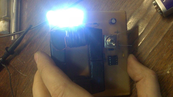
Few videos showing a working device. What's an IC worth: $0.924

I have not yet built this one, might give it a go:


I need to add Battery Pins:


MC34063AP


The Datasheet seems pretty straightforward. In the "Application Information" section, there are several schematics which is similar with external Switching:


Battery Pins added:


Maybe this little bit might be helpful, maybe we may learn something like you say Jagau.

   Chris

Attached Files

Chris posted this 12 October 2018

Hey Guys,

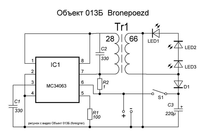
The following Schematic:


is the Schematic for the following Video:


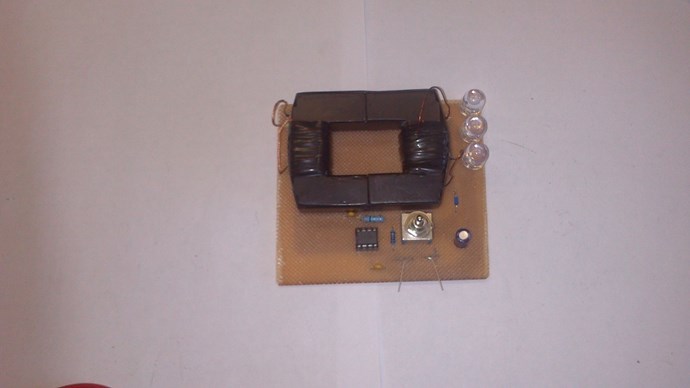
This is the PCB Layout:


These images were copied and archived by myself from the original "foreigner" posts on realstrannick.com ( Link no longer works ) many years ago, along with all the other images. I saw a date: 2013, but I don't think I copied them that long ago.

It is so critical to archive information! Its not long before some of it disappears!

The information in the: Lari Man YouTube channel, Published on Apr 1, 2015, is the original information. Original Video.

All I have done, is copy Lari Man's schematic, and draw so I can put in a layout I can replicate easily.

   Chris

Jagau posted this 12 October 2018

Transgeneration electromagnetic field energy is a very important document for me.
we have 3 coils on this new circuit with u 510 pf,
pin5 a voltage divider we are getting closer.

You know Chris for a coil that in closed circuit or open circuit the nodes and antinode are just reversed. At the quarter or the half wave of resonance, the driver only sees the impedance of the circuit, he does not know if the circuit is open or closed, it is what I call a blind circuit, and it works.
I like this

Jagau

Chris posted this 21 January 2019

My Friends,

I am going to take a little risk. These are not my Videos, they were removed a while back. Вадик Гук / Vadik Guk aka Delamorto.

Credit: https://www.youtube.com/user/VADIKGUK/videos


I shared some of my early work above. This does work, if one spends enough time on it. If you own these videos and want them removed please PM me and I will be happy to remove.

   Chris

Chris posted this 21 January 2019

My Friends,

Doing the best I can to share, but I still have a lot of problems I have yet to solve.

Under the Right conditions, Two Output Coils "Generate" more Electrical Energy than is Input to the System - Period.

My problem is, I cant predict this state, I can only work to this point by experiment. Thus my comment: "Requires some fiddling"

I call on good Electronics Engineers to be part of this mammoth effort, dedicate some of your time to help out. I cant do it all on my own. If I could hire a good EE, wow this would be awesome.

Please don't bother joining this effort if your not genuine, it will just result in your banning if you're a Troll - None here get Trolled.

   Chris

mrblobby posted this 31 May 2019

Posted this morning. "The principle of Roman’s Kornouhov & Tariel’s Kapanadze systems is now available to everyone."

Mitza84 posted this 19 October 2019

read very carefully the pdf he first write in russian and than is the eng translation . i hope that helps the conversation go trought all stages that it takes and the 4 videos from vadik guk that are posted here are related to this pdf he did them while chating on the forum with avalon.

Mitza

Mitza84 posted this 19 October 2019

My replication of the circuit is as follows i get it under 5 mA of consumtion the part of oscilation and the returning key is consuming a mbit much with the original design so i try to find oscillators that eat less energy so insted of that cd4069 you can use a ts555 with a simple schematic to trigger the transistor that return the energy.

Mitza

Attached Files

Vidura posted this 22 October 2019

Hi Mitza84.

Although I have not managed to make this device work( I have not spent too much time I must say), I will give you my point of view how it would be in theory, taking in account the latest results of investigation. The secret is in the coil, when it is in magnetic resonance a high potential will appear as an E-field, and will be captured by the grounded metal sheet. at the same time a negative pulse will be inverted by the Schmitt trigger and open the switch, which acts as synchronous rectifier and will loop the energy from the captured E-field to the positive rail.  This is only hypothetical for the moment, I hope that Chris will not bann me for posting to much theorylaughing.

Vidura

Fighter posted this 22 October 2019

Your post is precisely on subject and it's trying to explain the way a device work. So no worries Vidura, nobody is banned here for this kind of "theory" laughing

Mitza84 posted this 14 November 2020

vadik posted his video 3 and look at the description of the video maybe we can convince him to join us on aboveunity it would be very good .i have him on russian facebook il try to speak with him again but i know he is very busy and he is working on metal detectors for a while i was amazed to see him posted this video he told me he lost all the videos that he had about the device because he was haked or virus something like that .   this is his account on russian facebook     https://vk.com/delamorto

the schematic for this is this one   is tricky i got the consumption down to 1-2 mA but not self running yet

Hi Chris and hello guys this is how he describe the  operation of the device from above    delamorto:    Principle of operation - ferrite cups consist of two halves, the lower half contains a coil that excites the ferrites at the magnetostriction frequency, forcing it to rattle. This results in an RF magnetic field. It is induced on the second half of the ferrite cup, which enters into resonance and also rattles, there is a feedback coil in it, with which the energy is pulsed to the main capacitor, thereby compensating for the losses. It turns out a self-sufficient generator, the load of which is a white LED, the green LED indicates loss compensation (feedback). 

Mitza

Mitza84 posted this 14 November 2020

circuit diagram delamorto

Mitza

Wistiti posted this 15 November 2020

Hi friend! For sure I'm interested to see the circuit! Thank you for being active!

Vidura posted this 03 September 2018

Also  I wanted to point out that in the other device  that Sergei Panov has bought from Akula in one of the videos where Sergei is explaining the principal of operation , he shows a very similar concept to apply a gated pulsing on a fundamental resonant oscillation(10 to 50kHz) and explained that the pulses coming in this case from a teslacoil has to be applied in the second quadrant of the sinewave in order to get the power amplification in the lower frequency resonant circuit:

Vidura posted this 07 September 2018

Hi Jagau,

I checked the video again , the Value of the capacitor  is 510pF, not 300. Altough in my guess the frequency of the pulses is not that critical, but it might be a good idea to use the variable resistor on the supply of the ic as chris recomended and as used in the original schematic from Andrey:

I still dont have tried ,as i have to order the ic and the ferrite pot to do so. 

Regarding the coppersheet i think that it might couple with the asociated E-field without loading the souce, but this is just my guess.

wish you success with a replication if you have planned to do so.

Chris posted this 11 September 2018

Hey Jagau,

Thanks for sharing your calculations! I would have to consult my notes for the Frequency, but it was low. Of course the RC Time constant will vary from one to another device.

I sometimes leave a Terminal Block for the change of Capacitors in my Circuits, this helps change one out without too much trouble.

   Chris

Jagau posted this 12 October 2018

Pine 1 and 8 are short?
The diode of the Boost converter circuit is in the supply circuit?
No voltage divider on pin 5?
I'm not sure it works

Jagau

Vidura posted this 12 October 2018

I think you're on the right way with this, also we should keep in mind that in this device configuration there is a low resonant frequency

in the coils and the two electrolitic caps on both sides, and the very much faster pulses from the IC should be applied preferably at the second quadrant of the sinewave ,when the electric energy convertes in magnetic , in this circuit the timing is produced by a slight shifting past the sinepeak  due to the hysteresis of the internal comparator, and it might be possible to enhance the effect with a small additional delay on the outputvoltage sensing circuit. Only a idea , but could resultembarassed

Chris posted this 12 October 2018

My Friends,

@Vidura - Agreed, simplicity! See my YouTube link to the Richard Feynman video on simplicity:


@Jagau: fantastic observations! Thanks for sharing, although for some it may be knowledge already gained, for others this is eye opening. Like it is for myself! Thank You!


Please note: I am referencing my time on other forum and the Trolls I used to deal with.

Something I have really struggled with:

Why do some people have such difficulty with the invocation of Electrical Energy, via Electromagnetic Induction, being localised to a single device, right in-front of ones Eyes? After all, the Hydro-Electric Power Plant does exactly the same thing!


I cant get over how much some people wish this simple fact away! Making skeptics see the light is not my job. Making sense of non-sense is everyone's job.

The Magnetic Field, changing in Time and Conductors are all that's required for Electromagnetic Induction: Lenz's Law is the reason Energy Machines can be made to work! Without Lenz's law, we would not be able to make Machines like we see!

I am having a philosophical moment, apologies!

   Chris

Vidura posted this 30 November 2018


Hello ,
For all following this topics, I have thought that the way of driving this devices with a pulstrain in a certain area of the sinewave, but the conclusion i came to is that this is not the key of operating principal, experiments has shown that it is a very effective way of driving the oscillations but nothing more than that. I would like to share some thought's related to latest posts from Aloha about standing waves- slow magnetic waves. In my understanding it is all about the interaction between the transversal component and the longitudinal component of the inductors, where the former can be calculated using the well-known classical equations , but the latter seems to be a little more complex, as there is stated that the wire size, resistance and core material and duty cycle have also a important influence. The surprising low frequency of the longitudinal wave I can't still explain, but it is consistent with experimental results. The formulas proposed by Vyacheslav Gorchilin could be the missing link to bring this all together. He proposes that the longitudinal component is responsible for the formation of the standing waves , nodes and antinodes in the inductor, reflected between the ends(or joints of changing wire size). So it would be straightforward for somebody skilled in math's(not for me) to elaborate formulas for finding the correct relationship between the transversal and the longitudinal component of a given inductor and compare with experimental results. So the goal is to tune the inductor in a manner that both wave components interacts producing a positive feedback being in phase and resonance.
When we try to replicate the devices from melnichenkov, akula, ruslan kapanazde and others we find great difficulties to make them work if we have to find the correct coil construction by trying , winding and testing only, it might be that most of them simply won't work, we would have to cut wire pieces, reassemble and sweep frequencies and duty cycles….also the technique of move a connector on a uninsulated coil won't work with a longitudinal wave , as it still will be reflected at the very end of it. So if there is a mathematical instrument to predict the longitudinal behaviour of an inductor, it could be the solution to make this devices finally reproduceable, hopefully.
Regards Vidura.

Chris posted this 30 November 2018

Hey Vidura,

Voltage and Current is around 90 degrees out of phase in these resonant devices.

We must remember, the Current is the work component, it is Magnetomotive Force ( MMF ), and The Mr Preva Experiment shows us this, Currents are where we need to focus, to get the right Interactions.

Its not easy, and yes we have failures, you saw my latest failure.

If I may:


The Bottom Blue Trace, it an RC Time Constant, which means the Current will be lagging the Voltage by approximately 90 Degrees. Just part of the RC Time Constant of the Capacitor, Resistor and pull down Mosfet.

So the Phase shift will be something like:


All the Voltage Spikes are there, to try to Catch the point of Interaction. There the Voltage Slap, Time Rate of Change of the Coil with the lowest Inductance, connected to Pin 1, 7 and 8,  is trying to do the following things:

  1. Bring the Voltage Potential up as high as it can on the Lowest Inductance Coil.
  2. Time this so the Time is right, for interactions to occur at the maximum Potentials on both Coils, where Current is also at the optimum point.


Its not easy, I have had many failures, and still do. I truly believe if you follow the above, closely, and with Voltage and Current monitoring, you will see these effects very soon!

Remember: Once you catch this Wave, you will see a Sawtooth Waveform! This is where the Permanent Magnet falls through the Copper Tube, a Linear Rate of Current vs Voltage discharge, at which your Input is not being affected, its a response of the Configuration, not the Input. Currents will be equal in Magnitude ( AT ), but opposite. We have called this Magnetic Resonance here before.

I hope this helps.

   Chris

Vidura posted this 22 January 2019

Hey Chris, As you have stated taking some pieces of wires and start winding and trying is not the best solution to get this devices work, many of us have spent many hours, some with more, others (like me) with less success, but it is clearly tricky. At this time there are members with different skills and knowledge contributing on the Forum, and we are gaining better understanding from day to day. Regarding the specific devices discussed in this thread I have posted some opinions of how it could work, at this time I have to admit some of these where erroneous, others might apply in some aspects. Taking in account the posts from different threads I would point to the Interaction between the transverse and the longitudinal components of standing waves, it appears that a feedback can be achieved when the coils are tuned properly. We saw many successful replications from Russian developers, and I have a feeling that the calculations from Gorchilin could be helpful. I personally don't have the mathematical skills to apply this practically, but I guess for some members here it would not be difficult to work out a mathematical model to predict the behaviour of this devices, and find the critical points for a correct coils design and guidelines for tuning. So hopefully it we soon be possible to have more successful designs working all over the world. I am not referring to post blueprints and plans , but to gain understanding, and having some tools for correct designs not depending on trial and error only.Could there exist such a simple thing like a nomograph for this maybe?

Chris posted this 22 January 2019

Hey Vidura,

We know more today than yesterday, we have not just an accurate outline, but we have most of the requirements. I just cant build and go. It takes time to get to the end goal - All I have shared is accurate, its just not yet complete with a Build and Go model.

Its a build and Fiddle model, needs some work.

I would say my thread: Some Coils Buck and Some Coils Don't is around 98% of the workings needed.

   Chris

Chris posted this 31 May 2019

He is right MrBlooby,

Input MMF is opposed by Secondary One MMF but Assisted by Secondary Two MMF. The equation I have shared: 1 + -1 + 1 = 1.

He uses the term: "Tighten and Push" which is a good description.

   Chris

solarlab posted this 01 June 2019

Why is "Dmitry Maksimov's video" of such great interest and value? (IMHO)


One long standing fundamental question with respect to 'excess energy' generating devices is "Where does this extra energy come from?"

There have been many postulations (unproven theories?) over the years; some include an attempt at a mathematical proof while others show good demonstrations of excess energy production; but few, if any, combine a valid physical setup with accompanying (believable) math based upon known (orthadox) science, physics or engineering principles. This is not an easy task!

So; note that Dmitry Maksimov clearly demonstrates that by injecting a High Voltage Pulse into his (relatively simple) circuit coil arrangement; with correct timing; does indeed appear to increase the available power found in the circuit at minimal system power cost.

Dmitry is quick to realize the affect and, since his initial test circuit is straight forward, it may provide a very good platform for more expermentation and detailed analysis. For example; what effects might various HV pulse slopes, durations and injection phases have on the increased circuit power versus the cost.

Further, do these effects follow in some way, the mathematics - one example being the series of formulas and discussion found below.

'Time Varying Fields, Simple Waves'

"Likewise, a time varying electric field induces a magnetic field through the displacement current, even in the absence of the current J = 0. As is well known, the displacement current played a crucial role in Maxwell.s prediction that electromagnetic waves can propagate through vacuum."

Formula (4.3). [insert formula]
[note the time derivative part - faster rise/fall of higher voltage pulse => more excess power]
[also note - more pulses/sec => more excess power] [note - generating HV pulses requires minimal additional system power cost]

http://physics.usask.ca/~hirose/p812/notes/Ch4.pdf

and; 'Electromagnetic Momentum and Electron Inertia in a Current Circuit'

https://pdfs.semanticscholar.org/64e4/8cc38d68decf787fda1519db1f51f25a13a2.pdf

Continued... in some detail here (so as not to flood this thread): a FYI dump to my now abandonded "theory" thread...

SL

Chris posted this 20 October 2019

Hi Mitza84,

Vadik Guk showed a working machine, as have others using the same Circuit:

Of course a few minor modifications will be required depending on your coils. A 180 ohm resistor on Pin 8, but with work and study of others work, this will be easy to find.

I cant remember the turns, but again work and study will give you a figure that is good.

   Chris

Mitza84 posted this 20 October 2019

Thanks alot Chris i was thinking that this is the right one you used , Vadik used the one with the transistor posted in my pdf ,il put a photo also of the one he used it but if you get some minutes of work without battery or power supply that mean is easier to get it to work so we are on the right track with this schematic . his is more tricky and harder to get it working. so il try to make this one for now i hope il get it working with your help guys . thanks alot again Chris for the infos.

Mitza

Attached Files

Jagau posted this 21 October 2019

Hi Mitza84

this little lamp is a real challenge of energy management.

youy are welcome

Jagau 


Fighter posted this 21 October 2019

Hi Jorge,

Your device is very interesting, nice work !

I think your device deserves its own thread, if you want to create it and present your device and details feel free to do it, personally I'm looking forward to read your thread.

Regards,

Fighter

Fighter posted this 21 October 2019

@Mitza84, "seem to be" means we don't know if it's using Akula's principle or not until he is presenting his device, right ? The coil of the device looks a lot like Akula's coil and he's specifying it's "a very similar but simpler device".

@Jlezana, I encourage you to create a thread for presenting your device, I'm sure we all can learn from the details of your device, I find it very interesting.

Chris posted this 21 October 2019

@Jorge - Welcome!

Nice work! I left a message on your Channel, well done!

I agree with Fighter, I would like to give you your own thread, as your work does deserve it! Is this device something you want to further, to keep working on? If so I can help you with creating your own Thread if you wish?

Anyway, well done!

@Mitz - Like anything in life, learning to perfect something takes time. We can help, we all can help, but we must put the effort in to get there.

I will protect everyone here from Trolls, no one here gets trolled / Bullied by the non-believers. So please feel free to join, share, to add your bit.

   Chris

fer123 posted this 21 October 2019

Hola Jorge bienvenido al equipo de investigacion, esperamos que te sientas comodo y puedas desarrollarte al maximo. Saludos.

YoElMiCrO posted this 22 October 2019

Como todos también te doy la bienvenida.
Este foro es una comunidad muy unida y respetuosa.
Mientras mas seamos mejor.
Desde ya gracias.


YoElMiCrO

Mitza84 posted this 22 October 2019

Hi guys i made the schematic that Chris posted and i am having a little trouble when i connect the tc4069 part everything is turning of is like i make a short circuit on the device , i dont know what is wrong and the consumption go very very high.  if i conect just the oscillator side with the first coil everything is fine leds light well no trouble ,  i use a irf3025 mosfet  i still dont get how the part with tc4069 should return the power back .  maybe i can get some advice? 

Mitza

Attached Files

Mitza84 posted this 30 October 2019

HI raviope if you look at the pdf i posted above  you will see that you have LC resonance in delamorto circuit secondary coil is in paralel with a capacitor to create resonance and the bigest amplitude and then the energy is returned back to the source capacitor trought a transistor . anyway good point there well have to experiment to see how it goes . for the moment il move back home and i can experiment again after 1 november so il keep you guys updated when i start again with the experiments   i go in paralel with delamorto and melnicenko circuit from Chris and see wich perform beter. or wich i can manage to make it work .

Mitza

We're Light Years Ahead!
Members Online:

No one online at the moment


What is a Scalar:

In physics, scalars are physical quantities that are unaffected by changes to a vector space basis. Scalars are often accompanied by units of measurement, as in "10 cm". Examples of scalar quantities are mass, distance, charge, volume, time, speed, and the magnitude of physical vectors in general.

You need to forget the Non-Sense that some spout with out knowing the actual Definition of the word Scalar! Some people talk absolute Bull Sh*t!

The pressure P in the formula P = pgh, pgh is a scalar that tells you the amount of this squashing force per unit area in a fluid.

A Scalar, having both direction and magnitude, can be anything! The Magnetic Field, a Charge moving, yet some Numb Nuts think it means Magic Science!

Message from God:

Hello my children. This is Yahweh, the one true Lord. You have found creation's secret. Now share it peacefully with the world.

Ref: Message from God written inside the Human Genome

God be in my head, and in my thinking.

God be in my eyes, and in my looking.

God be in my mouth, and in my speaking.

Oh, God be in my heart, and in my understanding.

Your Support:

More than anything else, your contributions to this forum are most important! We are trying to actively get all visitors involved, but we do only have a few main contributors, which are very much appreciated! If you would like to see more pages with more detailed experiments and answers, perhaps a contribution of another type maybe possible:

PayPal De-Platformed me!

They REFUSE to tell me why!

We now use Wise!

Donate
Use E-Mail: Chris at aboveunity.com

The content I am sharing is not only unique, but is changing the world as we know it! Please Support Us!

Thank You So Much!

Weeks High Earners:
The great Nikola Tesla:

Ere many generations pass, our machinery will be driven by a power obtainable at any point of the universe. This idea is not novel. Men have been led to it long ago by instinct or reason. It has been expressed in many ways, and in many places, in the history of old and new. We find it in the delightful myth of Antheus, who drives power from the earth; we find it among the subtle speculations of one of your splendid mathematicians, and in many hints and statements of thinkers of the present time. Throughout space there is energy. Is this energy static or kinetic? If static, our hopes are in vain; if kinetic - and this we know it is for certain - then it is a mere question of time when men will succeed in attaching their machinery to the very wheelwork of nature.

Experiments With Alternate Currents Of High Potential And High Frequency (February 1892).

Close