Akula's circuits- is this the principle?

  • 10K Views
  • Last Post 19 November 2020
Vidura posted this 03 September 2018

Hello Team, after watching one of Akulas videos several times(Trance and Resonance) I think to understand a little bit better the principals of operation, and so I will share this observations here, hopefully adding up some useful information. Specially this circuit which is quite simple seems to be good to grasp the principle how it works, and also is cheap and quickly for built, in order to try to replicate.

Edit: viewing the valuable information about andrey melnichenkow that Chris has posted it becomes obvious that the credits for this discovering and buildings are corresponding to him ,and not to Akula, who evidently has merely copied Andrey's work.

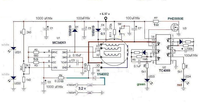
This is the schematic he is explaining on the video, I'll post the relevant details: the test points are highlighted in the colour of the scope traces.

He seems to point out that the CD4069  inverter is not needed, or not important for the basic operation, at least the shaded area, the inverter connected to the external FET forms a synchronous rectifier I would guess and could be probably replaced by a shottky rectifier if the CD4069 is not employed . The resonant oscillations are driven by the MC34063 chip, which  is an analogue dc-dc converter driver. Here the internal circuit from the datasheet:

Now this reveals a very important aspect of the operation principle: note that the fundamental frequency of resonance is 269Hz (the low value indicates that the coils are bucking), but the switching frequency of the converter is set to a much higher value by the timing capacitor C  on pin 3(for 300pF it is approximately 25uS  Ton and 10uS Toff). The Inverting Comparator input on pin 5 will shut down the switching when a the threshold voltage on the output is reached. So when the output voltage downscaled by the resistor divider  on pin 5 becomes greater than the 1.25V internal reference, the driver shuts down. With this technique it can be achieved by adjusting the variable resistor , that the switching occurs predominantly at the lower halfwave of the cycle(in the case of the boost converter, where the pulses at the yellow highlighted test point are negative), which will maintain the fundamental resonant oscillation with a minimal expense of energy.

Another detail that has called my attention are the copper sheets inside of the bobbin, which are found on some other devices of Akula as well. I don't think that this is a emf shielding, more likely it forms a capacitance or capacitor in conjunction with the second sheet at the inner end of the second winding. This will of course have no effect at the fundamental oscillation of the coils at 270Hz, but referring to the switching period of the driver with a 35uS period it will have a mayor effect, and might be used in this design to achieve a capacitive coupling of the second coil.

Note that in the following screenshot the schematic sheet which is below the circuit in the video has two modifications marked:

First a resistor in series with the output Led's -likely a impedance correction

Second the variable resistor for the shut down signal is changed  to a diferent configuration - for a broader range of adjustment


I think that this particular circuit would be a good start point to experiment as the basic design is quite simple. And in my opinion first the coil set have to be tuned to the fundamental resonance frequency, which is the tricky part, then the adjustment of the driver pulses and load impedance should be easier.

Order By: Standard | Newest | Votes
Vidura posted this 03 September 2018

Also  I wanted to point out that in the other device  that Sergei Panov has bought from Akula in one of the videos where Sergei is explaining the principal of operation , he shows a very similar concept to apply a gated pulsing on a fundamental resonant oscillation(10 to 50kHz) and explained that the pulses coming in this case from a teslacoil has to be applied in the second quadrant of the sinewave in order to get the power amplification in the lower frequency resonant circuit:

Vidura posted this 03 September 2018

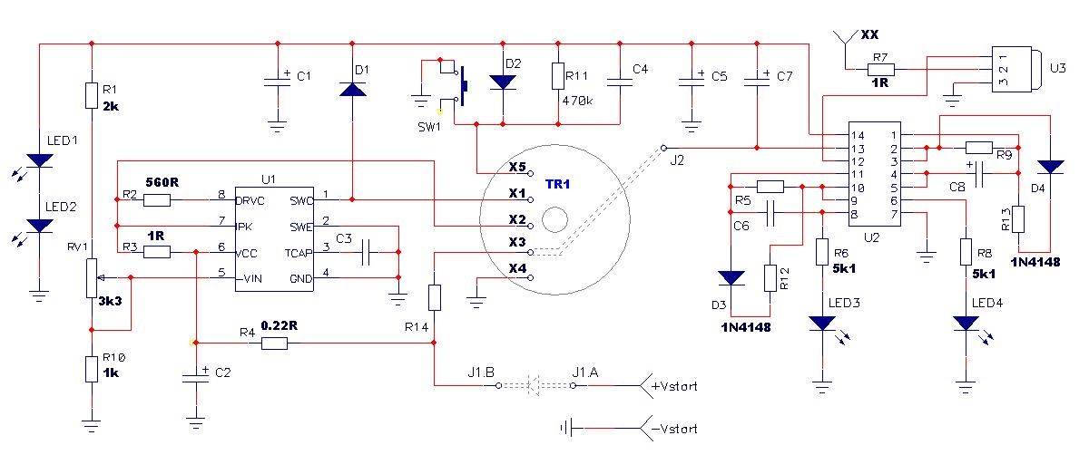
here I have found a clearer schematic of the flashlight circuit, where the components values are better readable.

  • Liked by
  • solarlab
  • Augenblick
Chris posted this 03 September 2018

Hi Vidura,

I replicated this circuit. Its a little difficult to get to the right working conditions if, like me ones electronics skills are only satisfactory.

I found putting a Variable Resistor on Pin 5 of the IC, I believe it was without consulting my notes, was a great help.

The Top Rail must be bought down for this Circuit to work, which initially is very un-intiutive until one finds that this Circuit can not work unless a Current is drawn, creating a Magnetic Field, "Generating" Energy to thus in-turn Charge the caps.

This lowering of the voltage also makes the IC increase in Frequency, via the Sensing Pin.

I spent a lot of time on my replication, but I learnt a lot!

I shouldn't, this will open doors for Trolls to discredit, but a video to share. Some of my very early progress: 


This was way back, years ago, when I first started replicating Akula's work. I spent a lot of time, but eventually, got it working.


Please remember, this is exactly the same as, and a copy from Andrey Melnichenko's work. Akula took Andrey Melnichenko's work, never gave him credit as far as I know, and portrayed it as his own:


P.S: Do you recognise this guy: Arthur Trankle of STEHO Energy?


I hope this helps a little?

   Chris

  • Liked by
  • solarlab
  • Augenblick
Chris posted this 04 September 2018

Backups are important, data retention is critical!

Some more, of the original hand written notes: 


These notes were marked as: "Manual". More notes marked as "Schematic"


More notes, marked as: "Foto"


You already have the Videos.

A special thanks to the person that shared this data many years ago! I found this data very valuable and I am sure others will also!

   Chris

Vidura posted this 05 September 2018

Thank's Chris for this Information, it's true that it might attract the attention of some Troll, but the most important is that it can help to get better understanding of the principals ,and encourage to more replications. If the members of the Forum are helping and supporting each others, it will be easy to deal with the Trolls!

Chris posted this 05 September 2018

Hi Vidura, very wise words my friend!

   Chris

  • Liked by
  • Augenblick
Jagau posted this 05 September 2018

the schematic that you put on the site help me better understand this project
thank you Chris

p.s. I learn to make youtube if you have stuff I'm interested!

Jagau

  • Liked by
  • Chris
  • Augenblick
Jagau posted this 06 September 2018


Hy Vidura


Very interesting diagram, I can not read correctly at pin 3 the capacitor,

is that you will have another picture more clear but I see that you wrote further in your post 300 pf is it?
thank you for the diagram.

Jagau
 

  • Liked by
  • Chris
  • Augenblick
Jagau posted this 06 September 2018


about EMI shieldind a possible explanation, see what they wrote in my electronic book,

Shields also intercept radiated noise and return it to its source through a low impedance.

Thus the need for a low resistance ground back to the source using the shortest possible path.

Jagau

Vidura posted this 07 September 2018

Hi Jagau,

I checked the video again , the Value of the capacitor  is 510pF, not 300. Altough in my guess the frequency of the pulses is not that critical, but it might be a good idea to use the variable resistor on the supply of the ic as chris recomended and as used in the original schematic from Andrey:

I still dont have tried ,as i have to order the ic and the ferrite pot to do so. 

Regarding the coppersheet i think that it might couple with the asociated E-field without loading the souce, but this is just my guess.

wish you success with a replication if you have planned to do so.

Chris posted this 07 September 2018

You Guys are just awesome!

I saw none of this cooperation whatsoever on the other forums! I have worked by myself for many years, isolated, taking many years to achieve simple things, you guys doing this together are making huge progress in only days!

I am a proud man to call you all my friends!

As we have learned in The Mr Preva Experiment and other threads here @ Aboveunity.com, the Currents in the Coils are the key factor.

  1. One Current ( I ) moving to the left.
  2. One Current ( I ) moving to the right.

Both Output Coils have individual Output Characteristics! Voltage is a Polarity, it can be Increased or Decreased. This is just a Geometry. Voltage is a Non Work related Quantity, stepping up or down at any time with some simple changes.

Current is a Work related Quantity, and we already know how to Amplify it, it is very easy to do!


CD may like to comment on this? My Thread: Some Coils Buck and some Coils DONT - Possibly may be one our sites greatest resources for those wanting to learn about these Currents in these Coils!

   Chris

Jagau posted this 07 September 2018

In this last schematic Chris we have 3 vectors identified by H1 H2 and H3
does that mean that we are creating a new H4 vector or we have an H3 current amplifier ??.
It is clear that the 3 coils are in series.

@  Yes I am building this very interesting project


Jagau

  • Liked by
  • Chris
  • Augenblick
Chris posted this 07 September 2018

Hi Jagau,

CD is correct. The Vectors are slightly confusing, normally the symbol ( H )  would be associated with the Magnetic Field Strength as you know. However, in this case we are specifically seeing an Arrow in the direction of the Current. We do, however, see the Curl of the Magnetic Field to indicate the Magnetic component also.

If we review the equation and substitute ( H ) with ( I ), because the symbol for Current is ( I ), and also some quotes:

I1 + I2 + I3 = I3


Keep in mind, a standard Electric Transformer,.


Lets imagine the Current as M.M.F, Magnetomotive Force, because it is, and look for a Hole:

I1 + I2 = 0

The answer is Zero because I1 is Positive and I2 is negative, this is one way to look at Current Vectors of a Transformer: 


Each Current Vector, one in the Positive Direction and one in the Negative Direction Cancel each other out. Thus, my previous use of

1 + -1 = 0


Or, another way to look at this, and a huge push with a big stick for those that are new to this, is Parasitic Inductance:


Lets imagine, we have a very high speed Circuit requirement, very basic layout of two singular sub circuits above. We have our Traces, Copper Busses on the PCB too close to each other, and the operational frequencies are very different of the two sub circuits.

One circuit is 10KHz and one 50MHz.

We will have massive problems with Stray Inductance and get a lot of noise on the Sub Circuits, simple because of the inductances and the Time Rate of Change of the Magnetic Field created bu the Currents in each Sub Circuit.

Importantly, the Signals will also be equal and opposite this the Arrows to indicate the Vectors of the Noise caused by the Parasitic Inductance.

Some take Rabbit holes, call this Capacitive Coupling, and it is, but remember, E and B are the same thing, one is the other, at 90 degrees. Move one and we see the other.

Remember what Floyd Sweet told us:


THE FALLACY OF DISPLACEMENT CURRENT


Conventional electromagnetic theory proposes that when an electric current flows down a wire into a capacitor it spreads out across the plate, producing an electric charge on the plate which in turn leads to an electric field between the capacitor plates. The valuable concept of continuity is then retained by postulating "after Maxwell" a displacement current. This current is a manipulation of the electric field ( E ) between the capacitor plates which has the dimensions of electric current and completes the flow of electricity in the circuit. This approach permits us to retain Kirchhoff's laws and other valuable concepts even though superficially it appears that at the capacitor there is a break in the continuous flow of electric current.

The flaw in this model appears when we notice that the current entered the capacitor at only one point on the capacitor plate.

We then are left with the major difficulty of explaining how the electric charge flowing down the wire suddenly distributes itself uniformly across the entire capacitor plate, at a velocity in excess of the speed of light. This paradoxical situation is created by a flaw in the basic model.

Work in high speed logic conducted by Ivor Catt has shown that the model of lumped capacitance is faulty and displacement current is an artefact of the faulty model.

Since any capacitor behaves similarly to a transmission line it is no more necessary to postulate a displacement current for the capacitor than it is necessary to do so for a transmission line. The excision of "displacement current" from electromagnetic theory has been based on arguments which are independent of the classic dispute over whether the electric current causes the electromagnetic field, or vice versa.


Why is Ivor Catt famous? Because he worked in High Speed Logic, to do what? Solve many of the Parasitic problems associated in IC's. How did he solve these problems? By understanding the Cause and Effect of the Time Rate of Change of the Magnetic Field.

In completion of the source problem, we see an additional Current Vector, thus an Induced Current via Electromagnetic Induction. We see a Gain in Current because:

1 + -1 + 1 = 1


Or:


I1 + I2 + I3 = I3


We see a Gain in Magnetomotive Force, a leverage, where a standard Transformer uses all of its Magnetomotive Force and can never be over unity, because we imbalance our forces, we now see gains. We have left over MMF!

Please Note:

One must think Electromagnetically Induced Currents! Not Forced Currents. Please note, these Coils are not Bucking because we make them Buck, this is entirely an Induced effect.

The introduction of a Third Coil, and the Electromagnetically Induced Effects of the Third Coil satisfy's Newton's hidden Law's of Motion:

Action, Reaction and Counter-Reaction


Voltage Polarity and Current Polarity can be in very different Directions!

   Chris

Vidura posted this 08 September 2018

Regarding the three coils from this  basic schematic from Andrey i would like to share some thoughts about including the context of the boost converter.

when wee look at the first step of swtiching: S1 is open and S3 closed ,all three coils will build up a current= magnetic field, but as two of the coils are opposed there B fields cancels each other, but do not eliminate it, as current= magnetic field is present.This also will cancel the impedance of the opposed two coils(exept  I2R losses)(H1+H2=0), and the overall impedance will be only the corresponding to L3 (H3) . This will allow a very fast charging of the inductors.

now let's look at the second step of switching(remember at this moment current is flowing thru all coils): S2 closes shorting coil L2 backlooping the flowing current to itself, simultaneously S1 opens interrupting the currentflow to ground, and thus giving rise to the BEMF which provides current flowing thru the diode to the load. But as L2 is shorted out in this instant the MMF of L1 and L3 wich are not opposing will add to the value of 2 * H3 doubling the output. so it should be possible to feed back a part of it to the source  and keep the device running.

If i made some mistake in this assumptions your corrections are welcomewink

Chris posted this 08 September 2018

Hey Vidura,

When I first started looking at this circuit, I was in an undecided state as to the timing of the switches.

I felt as if this was a Pseudo Circuit, to give guidance. Reason being, shorting L2 via S2 at On time or at off time made no real sense other than Inductance change in the total Coils Inductance.

Inductance change, depending on where the Magnetic Field is, does make some sense, but was it enough to see a gain on the output? My initial experiments did not show any good evidence.

It was the study of, and replication of this circuit that gave me the answers!


The 4069 Hex Inverter brings down the Top Rail as determined by the polarity on C2.


When tuned, this is the blue Sinusoidal signal, seen here:


Which is also impressed, and seen, on the Yellow trace. We all know, but others following, Electromagnetic Induction, its going to happen as explained above!

C2 can only discharge through R3 ( 1 Ohm ) then to X2, which has 2x Coils indicated in series, out to X1 up to D1 and then to Ground via U3. Of course U3 is switched by U2, the 4069 Hex Inverter. So if you like this is a feed back Oscillator, a slightly over complicated Voltage Controlled Oscillator.

The Magnetic Field and thus the Current rising and decaying sinusoidaly via 2x Coils, or twice the inductance of the other Coil according to our above diagram.

Current in the other Coil, connected to X0 flows in the opposite direction, this Current Charges the Cap, C2. We seem to see a problem here however... This makes no sense for the IC U1, the MC34063.

All Buck Boost converters are Current based, or Magnetic Field based devices. Their efficiency comes from the Efficient use of Electromagnetic induction. Short Sharp Pulses, which is what the MC34063 is designed for, requires a low inductance coil.

We have our answer here:


The Coils are not drawn correctly on the above Circuit layout. The Coil with the lower inductance needs to be Pin 1, the DC Boost Converter Coil. This is a critical and common theme on all devices. Short Sharp Pulses need a low inductance.

A sharp pulse on a Low inductance Coil will Induce a Higher Voltage on the Higher Inductance Coil.

Current then can increase further because: I = V / R

where in this case R is low anyway.

The Arrow and indication of "Negative Back EMF" charges the Cap C2, this is "Negative Current" which we saw in The Mr Preva Experiment, and also in my Thread, Some Coils Buck and Some Coils DONT.

Positive Current and Negative Current are doing a Push Pull, topping up Caps at each part cycle.

The Equation:

l1 + l2 + l3 = I3


We have I3 "Generating" the Device Run Energy! This is our Gain.


Its worth noting, Akula had a few go's at this:


I hope what I have shared does not confuse anyone? I hope its useful and insightful...

   Chris

Jagau posted this 11 September 2018

I made some calculations on the timing capacitor of the MC 34063
and I get between 40 and 44 kilohertz for 510 picofarad.
Do you get the same frequency?

This would make sense since the final frequency must be 269 hertz if we take into account

the word of wisdom!

Jagau

Chris posted this 11 September 2018

Hey Jagau,

Thanks for sharing your calculations! I would have to consult my notes for the Frequency, but it was low. Of course the RC Time constant will vary from one to another device.

I sometimes leave a Terminal Block for the change of Capacitors in my Circuits, this helps change one out without too much trouble.

   Chris

Vidura posted this 12 September 2018

Hi Jagau 

Regarding the Mc34063 IC find the datasheet attached below. There is a graph where Ton and Toff  can be approximately seen. As it is an analogue device the timing is given by the charge and discharge time of the capacitor on pin 3 and thus it is also influenced by the supply voltage of the device. You can use a variable resistor on pin 6 (Vcc) for fine tuning, there might be some benefit if tuned to a harmonic of the fundamental resonance. The duty cycle is fixed in this device , it works in "hiccup mode" shutting down the oscillator when the threshold voltage on pin 5 is reached , this can be adjusted with the variable resistor  on the output voltage sensing line.

When properly tuned this will make self oscillating virtually any RCL circuit ,regardless what the fundamental frequency is. I still have not received the materials to try to replicate, i had a lot of work these days and not much time to continue. In my guess the critical thing is to get the coil set and the capacitors of the fundamental resonance circuit tuned. 

My impression was first that the inductance of this coils is  way to hi for a boost converter at this frequencies, but when i made a few tests with a simple setup and opposed coils (1:2 ratio ) i had some unusual effects. Anyway in my opinion the coils are in a different way shown in andrey's and akulas circuits, and this schematics have to been seen with some care, as ti seems that both of them have made contracts with steho energy, there might be important details hidden.

Attached Files

Jagau posted this 12 September 2018

Ok thank you Chris and Vidura for the return.
On the attached image would you have an idea if both coils are
54 uh or 54 mH also for 27uh or 27 mh,
Microhenry and millihenry is a big difference


P.S Thank you Vidura I already have the pdf of IC

Jagau

  • Liked by
  • Chris
  • Augenblick
Vidura posted this 12 September 2018

According to the nr of turns and coresize it is almost certainly mH.

  • Liked by
  • Augenblick
Chris posted this 12 September 2018

Hey Jagau,

Of course Core and so on can change the Inductance, however in my tests, the results showed turns on a similar core was very close.

We are dealing with mH.

μH, one would expect to see only a few turns.

I would suggest a simple experiment, wind 23 odd meters on a small core and measure. If an arm length is approximately One Meter, and there is 23 on one coil, then we saw 23 Meters approximately on the core.

   Chris


One of my Coils:


  • Liked by
  • solarlab
  • Augenblick
Vidura posted this 12 September 2018

An observation i made on the Akula video regarding the coils, Chris surely also noted: when the inductor is disassembled there are on the first coil 23m , perhaps a little less, in the second coil there are also about the same number or more movements of his arm. so it could be assumed that the inductance of both coils is pretty the same. We should not trust to much in the information of the schematics, as the intention seems not to be to make it easy to replicate and share. We should make our own tests and conclusions.

Chris posted this 12 September 2018

Hey Vidura,

Agreed, I believe, 23 for one and approximately 26 for the other without recounting.

It is very important that one coil have a greater Inductance by a Factor! This is really important:


Marked In Yellow and in Red, Energy is in the Inductance. Inductance and the difference of it at Time t, allows for the Induction of Voltage and therefore Currents as a result:


54mH   /   27mH   =   2


Noting, the above Diagram marked in Yellow and Red has a factor of 2 as the Energy Gain.

   Chris

  • Liked by
  • Augenblick
  • solarlab
Jagau posted this 12 October 2018

hi vidura indeed this schematic seems more interesting.

I'm waiting for my MC34063 to try it too.
Have you ever tried this schematic?

do you know where this 80 volts peak to peak comes from on the schematic?

Jagau

Chris posted this 12 October 2018

My Friends,

I was avoiding this, TinselKoala is the author of this schematic, his videos:


In the second video up from the bottom, at 0 : 38, TinselKoala says he has the larger Inductance on the Chip side and the lower Inductance on the  Mosfet side. We know this to be wrong, it needs to be the other way around!

TinselKoala claimed the units were running from the Local Radio Station's Broadcasting Antenna.

Golly... it's so easy to suspect _me_ of tuning to an external power source! Why don't you suspect Lari-Man, or Akula, or Ruslan, of doing the same thing? Since all of their circuits _do_ work as receivers of external power, and Ruslan even works for a commercial FM radio station !!

I changed C2 to 600 pF in order to get rid of the "double (even triple) peak" within the main pulses, lowering the resonant frequency of the primary tank, so now my scopeshot waveforms look almost exactly like Lari-Man's. I left C1 at 33 pF, and also changed the cheapo blue LEDs into even cheaper white ones. (The blue ones were so cheap they kept failing on me.) Here's a couple of photos of the board running on just over 5 V from a dead 9V battery, and the resulting scope trace.

I've also shot a video, which is being processed now and will be uploaded in a few minutes.

(edited to correct capacitor numbers... sorry about that...)

TinselKoala - Akula0083 30 Watt Self Running Generator


All I want to say, is make your own mind up. Try putting a Transistor Radio in a Microwave Oven:


That's right, a single celled organism can debunk the skeptics Radio Station Theory!

   Chris

  • Liked by
  • solarlab
  • Augenblick
Jagau posted this 12 October 2018

I do not know this TK but this circuit seems to have some errors.
The mosfet short circuit voltage at the entrance when activated ???
Copper foil are on L1 only should not be on L2 ????
The inductance ratio L1 / L2 gives it a voltage L1 80 v, P / P and has the output doubled and we read 2.5v p / p ?????

This circuit has too much error, I will keep the original.

Jagau

Chris posted this 12 October 2018

My Friends,

A Simpler Circuit:


I have all the files, will post in the next hr or so. Have to pop out soon:

   Chris


Light Up the Darkness!

Jagau posted this 12 October 2018

Pine 1 and 8 are short?
The diode of the Boost converter circuit is in the supply circuit?
No voltage divider on pin 5?
I'm not sure it works

Jagau

Chris posted this 12 October 2018

Hey Jagau,

Few videos showing a working device. What's an IC worth: $0.924

I have not yet built this one, might give it a go:


I need to add Battery Pins:


MC34063AP


The Datasheet seems pretty straightforward. In the "Application Information" section, there are several schematics which is similar with external Switching:


Battery Pins added:


Maybe this little bit might be helpful, maybe we may learn something like you say Jagau.

   Chris

Attached Files

Jagau posted this 12 October 2018

It is with discussions like this that we advance.
thanks for sharing.


I am experimenting with this IC and with the latest development

I will share interesting results .

Jagau

Jagau posted this 12 October 2018

When pin 1 and 8 are shortened we are in buck configuration (lower voltage out than in)
and the last scheme is in buck mode with voltage inversion.
It's a test to do.

Jagau

Vidura posted this 12 October 2018

Hi Jagau, if pin 5 is tied to ground, the shutdown is turnd off and pulses will be continuous, in my opinion this would take much more power from supply, and not produce the pulses in a specific area of the sine, like shown in the video.but it could be tested both ways.

Jagau posted this 12 October 2018

 Not necessarily Vidura


As you can see in the data sheets of the manufacturers in Boost mode
the voltage divider install on pin 5 determines the voltage gain.

I did the 2 while experimenting and it is also like this that the schematic of Akula works.


I built this simple circuit to understand how the MC34063 works


you will notice that I am using a schottky diode. And change 7K resistor by variable one.

The way akula did this is to adjust the output voltage with the variable resistor, so as not to saturate the ferrite, I could verify this with my last experiences. if we place only one or no resistance directly to ground, we have the maximum voltage at the output, so we can not manage the excess energy without wasting it. So you can adjust your voltage out. and get better energy management.
Well it's my point of view I can be wrong but date my experiences is what it gives me.

Yes of course there is a lot of ways to make it work, but I'm going back to the Akula circuit.

I am still learning too this IC and with you help it go faster.

Jagau

Vidura posted this 12 October 2018

@Chris: 

Edit: I have reviewed the datasheet, the diagram is for the polarity inverted boost circuit , it seems to be right in this case, and the Ipk sense is Vcc reverenced, the resistor is correctly on the positive rail.

I am in doubt if there is an error in this diagram from the datasheet:

Here is  pin 4 which is the ground connection of the IC connected to the output; This configuration gives negative output certainly, and the IC would be floating on the output voltage level.

Due to trouble with my internet connection i could not see well earlier the simplified circuit you have posted, If i understand right this would operate in singlepuls mode, where each pulse is shutdown when the tresholdd on the Isense pin is reached. But is the  isense not internally ground reverenced? If it is the current sense resistor should be on the switching emitter, pin 2 ?

Jagau posted this 12 October 2018

Hello vidura I modify my post reread the bottom of the schematic you will understand.
Do not forget that I operate in boost mode and not in Buck mode as in your last circuit.

Jagau

Vidura posted this 12 October 2018

I think you're on the right way with this, also we should keep in mind that in this device configuration there is a low resonant frequency

in the coils and the two electrolitic caps on both sides, and the very much faster pulses from the IC should be applied preferably at the second quadrant of the sinewave ,when the electric energy convertes in magnetic , in this circuit the timing is produced by a slight shifting past the sinepeak  due to the hysteresis of the internal comparator, and it might be possible to enhance the effect with a small additional delay on the outputvoltage sensing circuit. Only a idea , but could resultembarassed

Jagau posted this 12 October 2018

Yes Vidura
Looks like you read my thoughts.
I'm wondering why he put sense resistor at 0.33 ohms?

All the circuits I've seen and try recommend .2 or .22 ohms, maybe the answer to what you propose.
Yet another great experience to do.

Jagau

Chris posted this 12 October 2018

Hey Guys,

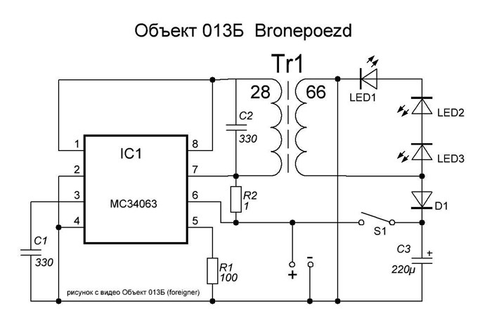
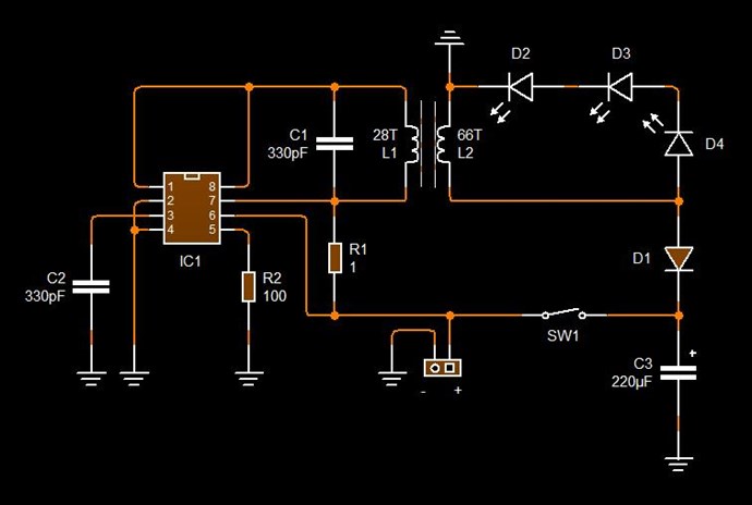
The following Schematic:


is the Schematic for the following Video:


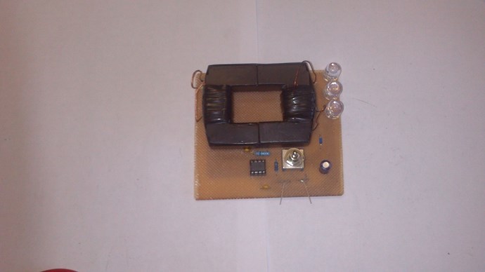
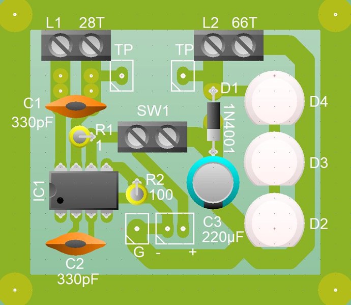
This is the PCB Layout:


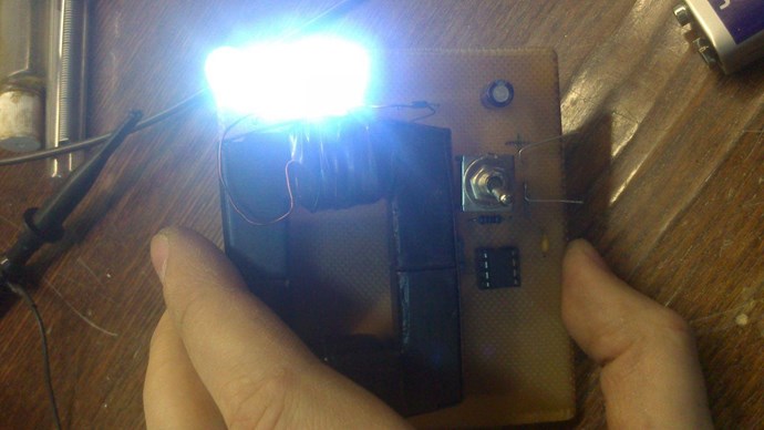
These images were copied and archived by myself from the original "foreigner" posts on realstrannick.com ( Link no longer works ) many years ago, along with all the other images. I saw a date: 2013, but I don't think I copied them that long ago.

It is so critical to archive information! Its not long before some of it disappears!

The information in the: Lari Man YouTube channel, Published on Apr 1, 2015, is the original information. Original Video.

All I have done, is copy Lari Man's schematic, and draw so I can put in a layout I can replicate easily.

   Chris

Chris posted this 12 October 2018

@All - Isn't it ironic that the MC34063 is a Buck Boost IC!

If one follows the schematic for the Lari Man Circuit, and also the MC34063 IC, one will see at on time, the two coils are shorted together.

Ironic just doesn't quite describe the situation.

Andrey Melnichenko was showing working devices way back in and around 2003 using the very same IC:


Using the: TS34063 IC, the date marked was: 12/10/2007, but I copied these documents well before this I am sure! This was from Andrey Melnichenko's original website, created: 18/10/2003.

Reference Andrey Melnichenko's document: Andrei Melnichenko Inventions

So, my friends, I think we need to get a move on, catch up. We have some 10+ years of catch up to do!

   Chris

Vidura posted this 12 October 2018

Looks great, i love the simplicity of the circuit.in one scope shot it is clearly visible that the majority of pulses are after the sinewave peak.at 3:11 in the video you see the pulstrain beginning just before the peak and continued all the falling curve.

Jagau posted this 12 October 2018

Transgeneration electromagnetic field energy is a very important document for me.
we have 3 coils on this new circuit with u 510 pf,
pin5 a voltage divider we are getting closer.

You know Chris for a coil that in closed circuit or open circuit the nodes and antinode are just reversed. At the quarter or the half wave of resonance, the driver only sees the impedance of the circuit, he does not know if the circuit is open or closed, it is what I call a blind circuit, and it works.
I like this

Jagau

Chris posted this 12 October 2018

My Friends,

@Vidura - Agreed, simplicity! See my YouTube link to the Richard Feynman video on simplicity:


@Jagau: fantastic observations! Thanks for sharing, although for some it may be knowledge already gained, for others this is eye opening. Like it is for myself! Thank You!


Please note: I am referencing my time on other forum and the Trolls I used to deal with.

Something I have really struggled with:

Why do some people have such difficulty with the invocation of Electrical Energy, via Electromagnetic Induction, being localised to a single device, right in-front of ones Eyes? After all, the Hydro-Electric Power Plant does exactly the same thing!


I cant get over how much some people wish this simple fact away! Making skeptics see the light is not my job. Making sense of non-sense is everyone's job.

The Magnetic Field, changing in Time and Conductors are all that's required for Electromagnetic Induction: Lenz's Law is the reason Energy Machines can be made to work! Without Lenz's law, we would not be able to make Machines like we see!

I am having a philosophical moment, apologies!

   Chris

Vidura posted this 30 November 2018


Hello ,
For all following this topics, I have thought that the way of driving this devices with a pulstrain in a certain area of the sinewave, but the conclusion i came to is that this is not the key of operating principal, experiments has shown that it is a very effective way of driving the oscillations but nothing more than that. I would like to share some thought's related to latest posts from Aloha about standing waves- slow magnetic waves. In my understanding it is all about the interaction between the transversal component and the longitudinal component of the inductors, where the former can be calculated using the well-known classical equations , but the latter seems to be a little more complex, as there is stated that the wire size, resistance and core material and duty cycle have also a important influence. The surprising low frequency of the longitudinal wave I can't still explain, but it is consistent with experimental results. The formulas proposed by Vyacheslav Gorchilin could be the missing link to bring this all together. He proposes that the longitudinal component is responsible for the formation of the standing waves , nodes and antinodes in the inductor, reflected between the ends(or joints of changing wire size). So it would be straightforward for somebody skilled in math's(not for me) to elaborate formulas for finding the correct relationship between the transversal and the longitudinal component of a given inductor and compare with experimental results. So the goal is to tune the inductor in a manner that both wave components interacts producing a positive feedback being in phase and resonance.
When we try to replicate the devices from melnichenkov, akula, ruslan kapanazde and others we find great difficulties to make them work if we have to find the correct coil construction by trying , winding and testing only, it might be that most of them simply won't work, we would have to cut wire pieces, reassemble and sweep frequencies and duty cycles….also the technique of move a connector on a uninsulated coil won't work with a longitudinal wave , as it still will be reflected at the very end of it. So if there is a mathematical instrument to predict the longitudinal behaviour of an inductor, it could be the solution to make this devices finally reproduceable, hopefully.
Regards Vidura.

Chris posted this 30 November 2018

Hey Vidura,

Voltage and Current is around 90 degrees out of phase in these resonant devices.

We must remember, the Current is the work component, it is Magnetomotive Force ( MMF ), and The Mr Preva Experiment shows us this, Currents are where we need to focus, to get the right Interactions.

Its not easy, and yes we have failures, you saw my latest failure.

If I may:


The Bottom Blue Trace, it an RC Time Constant, which means the Current will be lagging the Voltage by approximately 90 Degrees. Just part of the RC Time Constant of the Capacitor, Resistor and pull down Mosfet.

So the Phase shift will be something like:


All the Voltage Spikes are there, to try to Catch the point of Interaction. There the Voltage Slap, Time Rate of Change of the Coil with the lowest Inductance, connected to Pin 1, 7 and 8,  is trying to do the following things:

  1. Bring the Voltage Potential up as high as it can on the Lowest Inductance Coil.
  2. Time this so the Time is right, for interactions to occur at the maximum Potentials on both Coils, where Current is also at the optimum point.


Its not easy, I have had many failures, and still do. I truly believe if you follow the above, closely, and with Voltage and Current monitoring, you will see these effects very soon!

Remember: Once you catch this Wave, you will see a Sawtooth Waveform! This is where the Permanent Magnet falls through the Copper Tube, a Linear Rate of Current vs Voltage discharge, at which your Input is not being affected, its a response of the Configuration, not the Input. Currents will be equal in Magnitude ( AT ), but opposite. We have called this Magnetic Resonance here before.

I hope this helps.

   Chris

Chris posted this 21 January 2019

My Friends,

I am going to take a little risk. These are not my Videos, they were removed a while back. Вадик Гук / Vadik Guk aka Delamorto.

Credit: https://www.youtube.com/user/VADIKGUK/videos


I shared some of my early work above. This does work, if one spends enough time on it. If you own these videos and want them removed please PM me and I will be happy to remove.

   Chris

Chris posted this 21 January 2019

My Friends,

The above videos were Akula's reason to make the video:


and, he then continued onto:


If I may point out:

  • The MC34063 IC is a DC to DC Converter Chip.
  • The On time is very short, in the region of 1% or less Duty Cycle.
  • The Two Coils have Inductive Interactions at every point in the Cycle.
  • Each Coil has On-Time and Off-Time. Both interacting with each other.
  • This device was originally shown by Andrey Melnichenko.


Electrical Energy is "Generated" during the Cycle. Voltage in this case must be sufficient to charge Capacitors: C2 and C5 so the positive terminal Voltage is at or just above the starting voltage. That's why L2 must have more turns, a Higher Voltage, a greater Inductance:


For example, 10 volts across the two Capacitors, C5 and C2 above, Divides the Voltage:


So L2 must have greater turns on it by a Factor. This depends on the Capacitance also, see above link for more information! So we see, Electrical Energy is "Generated" and this generation is a result of the Interactions between two Coils in Time.

   Chris 

Jagau posted this 21 January 2019

Since this circuit is a power management issue,

the best time I've done is 0.8% DTC
And what is surprising about the resonant frequency

should be just a little next to spare the milliampere for consumption.

Jagau

Chris posted this 21 January 2019

My Friends,

Doing the best I can to share, but I still have a lot of problems I have yet to solve.

Under the Right conditions, Two Output Coils "Generate" more Electrical Energy than is Input to the System - Period.

My problem is, I cant predict this state, I can only work to this point by experiment. Thus my comment: "Requires some fiddling"

I call on good Electronics Engineers to be part of this mammoth effort, dedicate some of your time to help out. I cant do it all on my own. If I could hire a good EE, wow this would be awesome.

Please don't bother joining this effort if your not genuine, it will just result in your banning if you're a Troll - None here get Trolled.

   Chris

Vidura posted this 22 January 2019

Hey Chris, As you have stated taking some pieces of wires and start winding and trying is not the best solution to get this devices work, many of us have spent many hours, some with more, others (like me) with less success, but it is clearly tricky. At this time there are members with different skills and knowledge contributing on the Forum, and we are gaining better understanding from day to day. Regarding the specific devices discussed in this thread I have posted some opinions of how it could work, at this time I have to admit some of these where erroneous, others might apply in some aspects. Taking in account the posts from different threads I would point to the Interaction between the transverse and the longitudinal components of standing waves, it appears that a feedback can be achieved when the coils are tuned properly. We saw many successful replications from Russian developers, and I have a feeling that the calculations from Gorchilin could be helpful. I personally don't have the mathematical skills to apply this practically, but I guess for some members here it would not be difficult to work out a mathematical model to predict the behaviour of this devices, and find the critical points for a correct coils design and guidelines for tuning. So hopefully it we soon be possible to have more successful designs working all over the world. I am not referring to post blueprints and plans , but to gain understanding, and having some tools for correct designs not depending on trial and error only.Could there exist such a simple thing like a nomograph for this maybe?

Chris posted this 22 January 2019

Hey Vidura,

We know more today than yesterday, we have not just an accurate outline, but we have most of the requirements. I just cant build and go. It takes time to get to the end goal - All I have shared is accurate, its just not yet complete with a Build and Go model.

Its a build and Fiddle model, needs some work.

I would say my thread: Some Coils Buck and Some Coils Don't is around 98% of the workings needed.

   Chris

We're Light Years Ahead!
Members Online:
What is a Scalar:

In physics, scalars are physical quantities that are unaffected by changes to a vector space basis. Scalars are often accompanied by units of measurement, as in "10 cm". Examples of scalar quantities are mass, distance, charge, volume, time, speed, and the magnitude of physical vectors in general.

You need to forget the Non-Sense that some spout with out knowing the actual Definition of the word Scalar! Some people talk absolute Bull Sh*t!

The pressure P in the formula P = pgh, pgh is a scalar that tells you the amount of this squashing force per unit area in a fluid.

A Scalar, having both direction and magnitude, can be anything! The Magnetic Field, a Charge moving, yet some Numb Nuts think it means Magic Science!

Message from God:

Hello my children. This is Yahweh, the one true Lord. You have found creation's secret. Now share it peacefully with the world.

Ref: Message from God written inside the Human Genome

God be in my head, and in my thinking.

God be in my eyes, and in my looking.

God be in my mouth, and in my speaking.

Oh, God be in my heart, and in my understanding.

Your Support:

More than anything else, your contributions to this forum are most important! We are trying to actively get all visitors involved, but we do only have a few main contributors, which are very much appreciated! If you would like to see more pages with more detailed experiments and answers, perhaps a contribution of another type maybe possible:

PayPal De-Platformed me!

They REFUSE to tell me why!

We now use Wise!

Donate
Use E-Mail: Chris at aboveunity.com

The content I am sharing is not only unique, but is changing the world as we know it! Please Support Us!

Thank You So Much!

Weeks High Earners:
The great Nikola Tesla:

Ere many generations pass, our machinery will be driven by a power obtainable at any point of the universe. This idea is not novel. Men have been led to it long ago by instinct or reason. It has been expressed in many ways, and in many places, in the history of old and new. We find it in the delightful myth of Antheus, who drives power from the earth; we find it among the subtle speculations of one of your splendid mathematicians, and in many hints and statements of thinkers of the present time. Throughout space there is energy. Is this energy static or kinetic? If static, our hopes are in vain; if kinetic - and this we know it is for certain - then it is a mere question of time when men will succeed in attaching their machinery to the very wheelwork of nature.

Experiments With Alternate Currents Of High Potential And High Frequency (February 1892).

Close