Akula's 30 W Lantern Chris's Replication

  • Topic Is Sticky
  • 7.5K Views
  • Last Post 17 October 2023
Chris posted this 30 March 2017

I am planning on sharing some work, work that was incomplete, simply because I got distracted and moved onto another project.

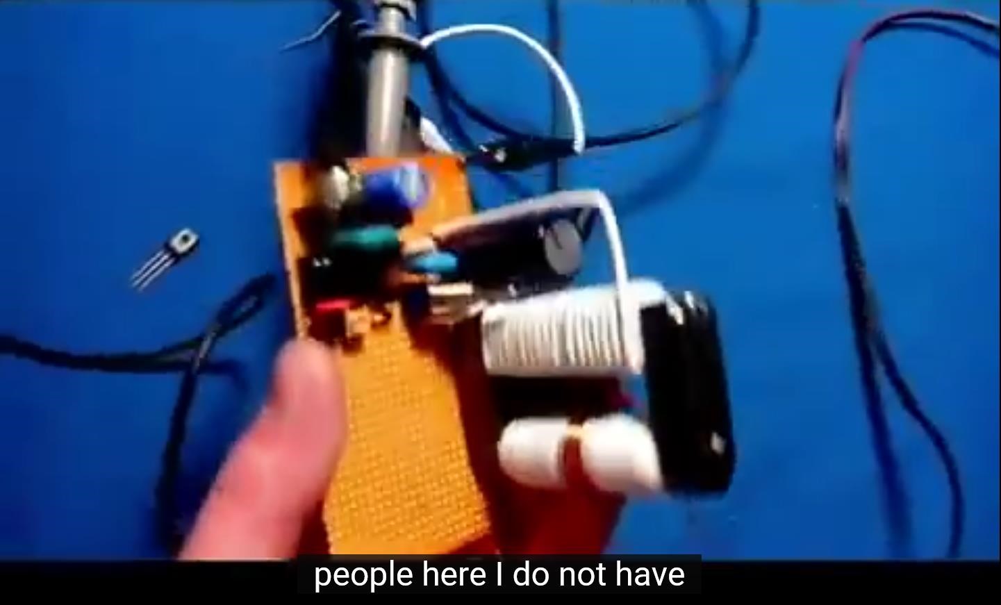
Although I did not finish the Akula 30 Watt Lantern, I did go a long way on it! Getting some very positive results. Just not getting a single board complete that runs itself indefinitely.

I am planning to share what I did to get these results. The basic steps I took, and the Goals I set for myself.

Under the Username "EMJunkie" I did a lot of work over at ou.com, shared a lot, but noticed many there really were not interested, and most were not doing any constructive work towards the effort to understand the Akula Work! Too many tools in the Garden Shed over there!

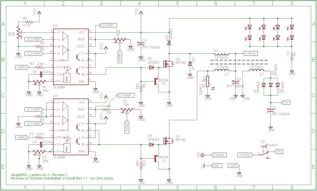
I did a lot of Circuit Analysis, in an attempt to understand what Akula was doing. I came up with the following circuit: Akula0083 30 Watt Self Running Generator


Just so you all know, the YouTube Channel "Akula Vids" was started by me, its my channel, saving all of Akula's Videos for the history record. I did this after noticing that some videos were disappearing, like someone was going through deleting them from YouTube.

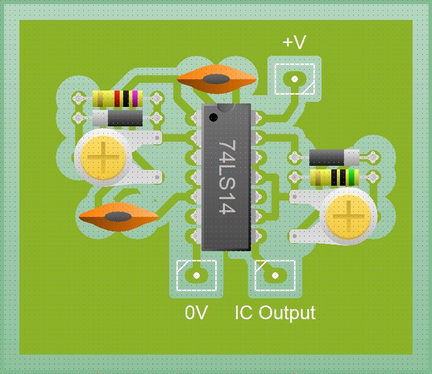
Akula built many Lanterns, if memory serves, as many as four. I am going to concerntrate on the most simple one:


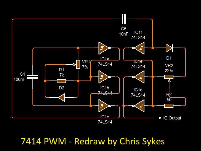
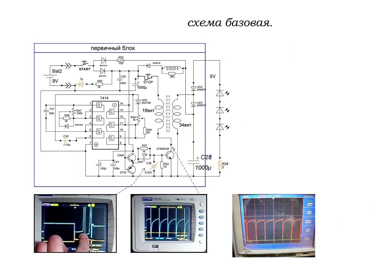
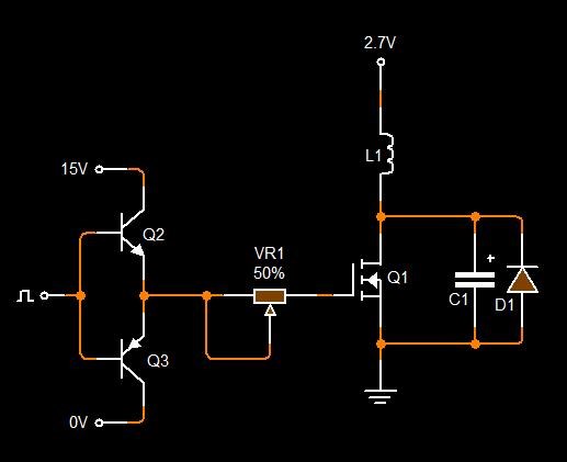
The Circuit for this Lantern, No#4:


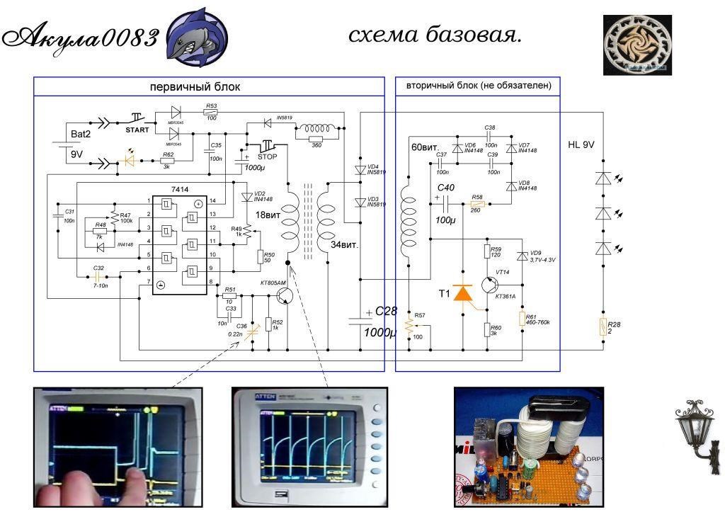
I believe this circuit is not 100% correct. There is no sign of the SCR, or any other switching circuitry surrounding the SCR.

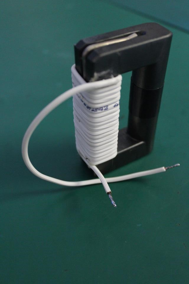
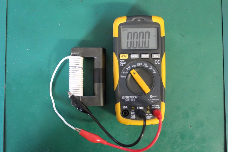
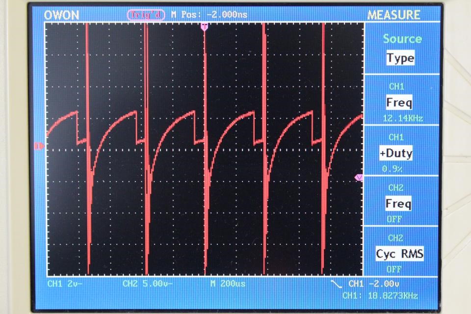
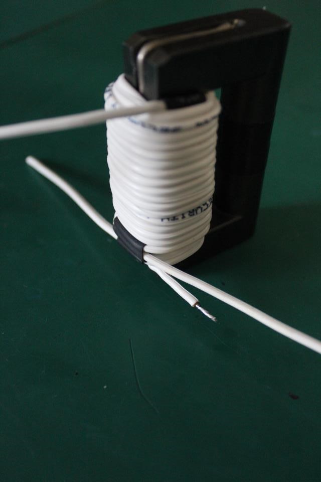
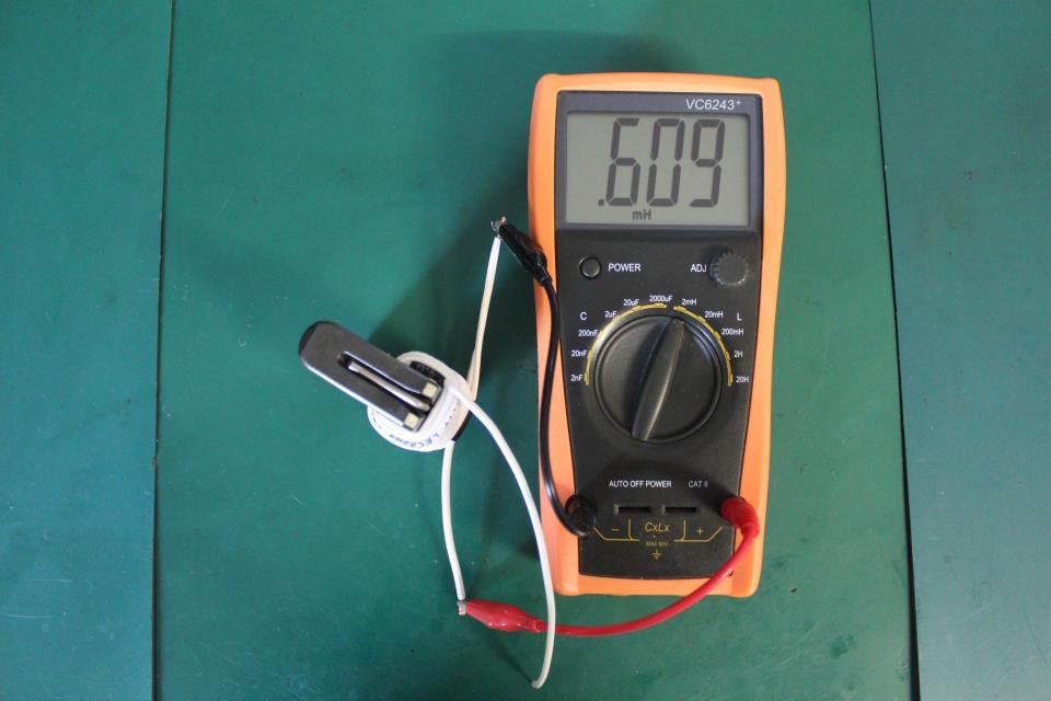
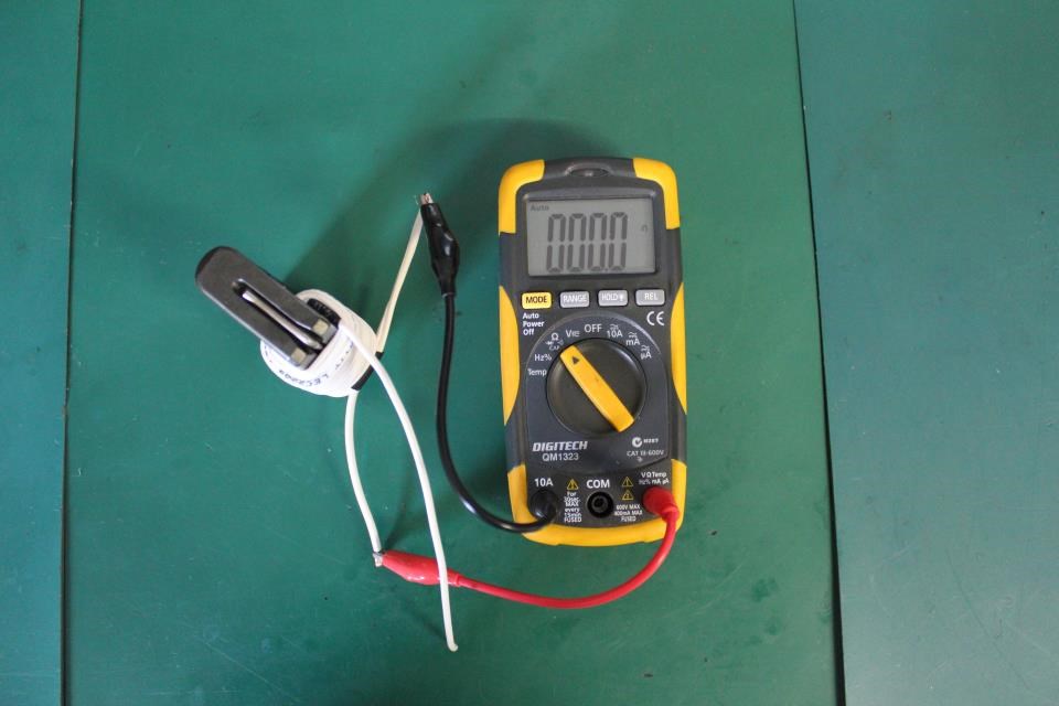
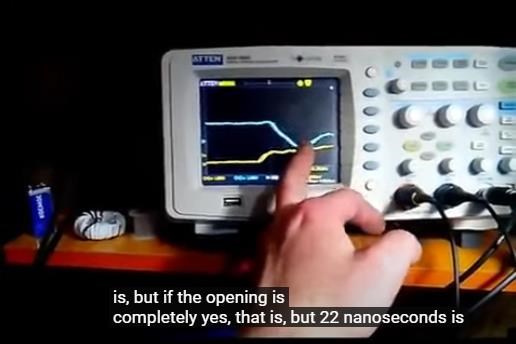
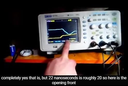
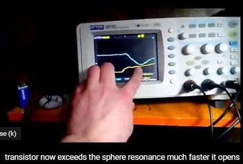
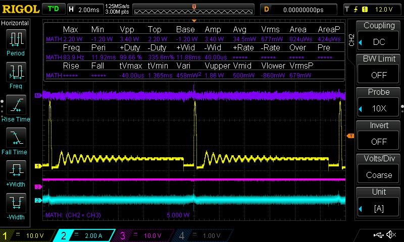
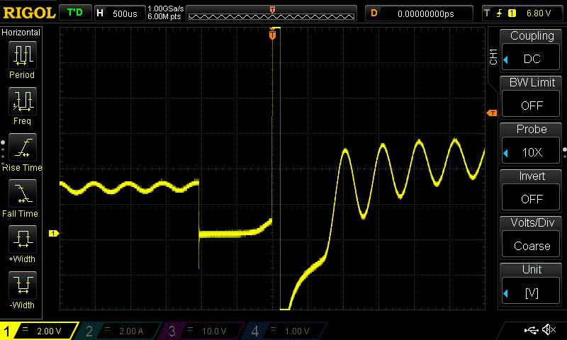
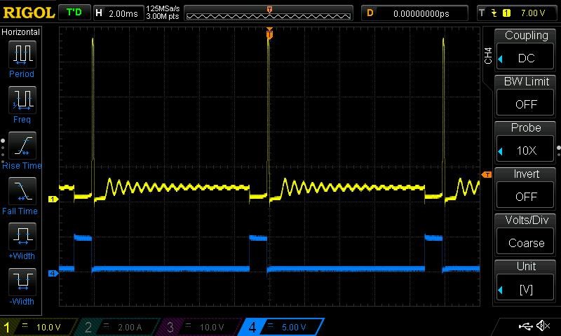
The Input Coil was 18 Turns, on a CRT TV Flyback Ferrite Transformer Core. Akula claimed to achieve "Ferro Resonance" in the Core, and showed some pretty detailed Scope Shots using very low input power:

In the recent light of Ruslans work, this has spurred me to continue, Also, I think we have a few interested persons here willing to replicate and work towards the end goal.

I will keep you posted.

   Chris


Order By: Standard | Newest | Votes
Chris posted this 11 October 2017

Step One

My Primary Coil, 18 Turns on a Ferrite CRT TV Transformer:


The Inductance:


The Resistance:


The coil statistics:

  • Turns: 18
  • Length: 1384mm
  • Diameter: 0.75mm
  • Inductance: 0.535 mH
  • Resistance: 0 Ohms read

More to come soon.

   Chris

Chris posted this 12 October 2017

Step Two

Replicate the Waveform Akula was trying show us! Understand what he was saying. 


Remember: A Mosfet or a Transistor is a Switch. It Chops Voltage, either On or Off, or somewhere in between!


The basic Circuit, the same as in the first post, but testing I use a Micro Controller, switching the Transistor shown in the Circuit above. Very simple.


My Input Frequency and Duty Cycle


The Waveform: (Probe was positioned at the Collector as was advised in the original Schematic)


  • Input:
       Amps: none on PSU
       Input Voltage: 2.7 Volts
       Frequency: 2,684Hz
       Duty Cycle: 16%


  • Switching:
      Transistor: TIP 122


My Frequency (2.684KHz) is a lot higher than Akula's (256.360Hz), also my duty Cycle. This could be a few things, Transistor, Coil and Ferrite may have different properties. But, the basic waveform is the same.

   Chris

Chris posted this 12 October 2017

Step Three

Wind the Secondary Coil. Akula covers the Secondary Coil with great detail. Saying things like "Timing", "Sufficient Electrons Moving" and so on. So, some work may be needed here. First wind may not be enough, nor might be the second.

I started with the same as Akula had: (17 and then 16 turns) 2 Layers:


Note: The Black Tape you can see is actually Heat Shrink. I put it over two Winds to hold the last wind in place. Looks a bit mess, but does its job well.

This is just a start and it may be enough to do what we need, or it may not.


  • Turns: 33
  • Length: 3008mm
  • Diameter: 0.75mm
  • Inductance: 0.608mH
  • Resistance: 0.1 Ohms Measured.

   Chris

Chris posted this 12 October 2017

Step Four

We know what the Base, or Gate signal to the Mosfet or Transistor must be now, found in Step Two, we have replicated the Waveform as was shown in the Video. Now we need to build a circuit around this signal.

Its worth noting, I have shown much of this already. The Circuit I have separated into smaller Sub Circuits. 

The PWM Circuit:


This Circuit is not optimised for my PWM, its a pseudo Circuit, to show the 7414 PWM Frequency and Duty Cycle.

Changing the Resistors (R1 VR1 and R2 and VR2) and the Capacitors (C1 and C5) should be enough to adjust for the Frequency and Duty Cycle I need.

The Output, or Feedback Circuit is pretty straight forward. It's worth noting, my progress was the same as Madsatbg's


   Chris


Chris posted this 23 October 2017

I was hoping to see some activity from others. CD and I are the only ones working on this from what I can tell.

Anyone else keen to join in?

   Chris

  • Liked by
  • ISLab
  • Augenblick
Chris posted this 10 April 2023

My Friends,

Life is all about achievement! Achievement gives Life Purpose!

We have seen after some effort, and time, others have made replications: around Nov 2020


They decided to hide, and keep secret the progress, keeping their so called Team Mates entirely in the dark about their success! I helped in the development of this device! I knew about it already!

I caught this person on a few misleading statements, and after that, this person deleted their thread, and deleted the information in the thread. Hiding this information, that was not theirs anyway, information that was given to them prior to them getting as far as they had:

My Friends,

Trust is something that must be earned, its easily tested, and many have shown how Un-Trust Worthy they really are!

A Self Running Machine was posted to a thread previously, and the thread was deleted. Deleted by the Thread Owner. I had given some constructive criticism, on the way the thread was handled. I posted the Secret that the Thread Owner was trying to avoid. Trying to claim as their own amazing discovery.


The thread was posted some time ago, November last year, and I posted an argument, showing that the discovery that was claimed was already known:


Oh My, what some people get up to:


So you see the secret, how it can lay right in front of your eyes and not notice it?

I replicated and also showed the secret:


This took me all of about three minutes to throw together.

Here is a simple analogy:


I have kept some information secret, not made some information known, so I can catch some people out when I need to!

As I pointed out, and this Ex-Member did not like, the Mosfet Control on Rise and Decay time is important. Akula gave us this information, as I have shown above! This Team Member that had agreed to the rules of the team, was not truthful and tried to keep secrets from other team members. Even though this person admitted on many occasions learning from others here! Do you think this is fair?

In a Mosfet, we have a Gate Capacitance, and with the addition of a Resistor, or a Variable Resistor, we can control how the Mosfet is Charged and Discharged. This controls the Rise and Decay Times of the Mosfet!


Where VR1 is configured to adjust the Rise and Decay time for the specified Mosfet. Q2 and 3 are a simple Mosfet Driver IC. R x C = T, in Seconds, so one can calculate this time by knowing your Mosfet Gate Capacitance. See Datasheet!


We have been told about this from Tom Bearden also:


Well, the actual video has been removed, Stupid Copy Right Claims! But here is another.

Many ran off, and sided with Liars and Cheats! CIA Spoofs!!!


I will remember who you are! Siding with Liars and Cheats will never earn you any brownies!

I wish more people would care as much for their Brothers and Sisters as they do for themselves!

Best Wishes,

   Chris

Chris posted this 17 April 2023

My Friends,

One of the best articles I have found, and of course pointing you toward the data sheet:

Transistor Switching Times:

For Transistor Switching Times, the switching speed of the device can be an important quantity. Consider the circuit in Fig. 8-18(a). When the base input current is applied, the transistor does not switch on immediately. Like frequency response, the Transistor Switching Times is affected by junction capacitance and the transit time of electrons across the junctions. The time between the application of the input pulse and commencement of collector current flow is termed the delay time (td), [see Fig. 8-18(b)]. Even when the transistor begins to switch on, a finite time elapses before IC reaches its maximum level. This is known as the rise time (tr). The rise time is specified as the time required for IC to go from 10% to 90% of its maximum level. As illustrated, the turn-on time (ton), is the sum of td and tr.

Transistor Switching Times


When the input current is switched off, IC does not go to zero until after a turn-off time toff, made up of a storage time (ts), and a fall time (tf), as illustrated. The fall time is specified as the time required for IC to go from 90% to 10% of its maximum level. The storage time is the result of charge carriers being trapped in the depletion region when a junction polarity is reversed.

When a transistor is in a saturated on condition, both the collector-base and emitter-base junctions are forward biased. At switch-off both junctions are reverse biased, and before IC begins to fall, the stored charge carriers must be withdrawn or made to recombine with opposite-type charge carriers.

 Transistor Switching Times


For a fast-switching transistor, ton and toff must be of the order of nanoseconds. The 2N3904 transistor data sheet portion in Fig. 8-­19 specifies the following Transistor Switching Times: td = 35 ns, tr = 35 ns, ts = 200 ns, and t= 50 ns.

Ref: Transistor Switching Times


And Akula's Video:


Transcription:

так и большую архив пока фонарики
добиваю так вот этот фонарь
более серьезный сейчас у меня здесь
кт805
стоит да это только для того чтобы
определиться с длительностью времени до
его открытия поэтому ставлю кт805 а
будет стоять потом рфк когда уже буду
точно знать время подберу и рывком ключа
из всех конденсаторов которые могут
воспринять обратный выброс
высоковольтный подходят только высоко
водные то есть на 400 вольт на 60 вольт
вот у меня сейчас на шестьдесят три
вольта стоит конденсатор он нормально то
есть вот такой хорошо воспринимает то
есть это на обратный по сама , лучше
ставить вот такие конденсаторы они лучше
тем что они не бумажные
gift между пластину войлок и большое
расстояние то есть они способны
воспринять импульс которых достигает 60
50 вольт и зарядиться не создавая
нагрузку все конденсаторы которые идут
на 16 вольт двадцать пять вольт 35 вольт
они слабы то есть 50 вольт в свыше 50
вольт они уже лучше воспринимают так вот
тут у меня получилось вот чего
здесь у меня генератор ставить вот тут
собран задающий генератор
низкочастотный который будет уже
управлять низко-частотным тиристором по
сама запятую дует импульсный саму запись
сначала буду брать со вторички заряжать
до 400 вольт а затем импульсно через
дроссель
уже кори корректировать конденсатор по
сама запятую и напряжение на нем
от него же сразу зависимо то есть стоит
система в ч вот оно то есть это аналог
манасян дэнси
генератор наносекундных импульсов но
почему я решил сделать это видео для
того чтобы показать как вот данный кусок
феррита заходит в резонанс и как это
зависит от времени для того чтоб все
перестали упираться 1 на секундные
импульсы
то есть они вообще здесь ни причём
длительность импульса выбирается
согласно индуктивности и соответственно
ферромагнитного сердечника то есть
самого феррита то есть кто то речь будет
идти не она на импульсах
я говорю что это аналог но это не
генератор на науку со
здесь будут импульса микросекунды вот я
сейчас покажу то есть я уже знаю просто
резонансную частоту этого феррита она
очень низкая так вот запускаем его и чем
мы видим вот вот это желтый это сигнал
на базе генератора
вот то что вот это синий это коллектор
этот час идет выброс свободной любовью
довольно таки высоковольтным получается
и он в принципе
из себя и представляет ферромагнитный
резонанс то есть вот эта амплитуда
никогда по своему размеру не превысит
ферромагнитный резонанс атакама в
принципе есть так ночью я хотел сказать
есть у меня сейчас стоит к тех 805
транзистор то есть для проверки
длительности импульса то есть у меня
сейчас 2 с половиной мили микросекунды
до
идет то есть 1 2 5 то есть получается 5
6 7 почти восемь у меня восемь
микросекунд у меня транзистор открыт и
и что мы видим у нас на наших этих
штучках вот вот такие штуки да то есть в
принципе все что и видят и не могут
понять почему они не могут обраткой
зажечь диоды
вот сейчас получается что транзистор
открывается намного быстрее
ферромагнитного резонанса
сейчас посмотрим длительность открытия
вот 50 наносекунд фронт открытие у нас
сейчас его увеличу вот так
вот 10 наносекунд и того фронт
составляет но если вот открытие
полностью да то есть но 22 наносекунду
грубо 20 так вот фронт открытия
транзистора сейчас превышает сферы
резонанс намного он быстрее открывается
эфире ты в принципе его не видят то есть
вот это открытие наша вот резкая не
видят сейчас мы то что мы видим у и ds
выброс это не уйду из нашего феррита х о
д с самой катушки то есть сейчас феррита
вообще пофиг чо происходит потому что во
первых длительность самого импульса
она тоже меньше ферро резонанс и наш
эфире ты просто стоят если они слегка
дергаются то они вообще сейчас не
участвуют вот в этих выбросах
и они по сути бестолковые поэтому
загнать их просто в обратку толку не
будет даже ими даже не зажечь и ни один
светодиод
теперь по поводу длительности то есть
нам необходимо же by практически без
затрат на развернуть ферриты
еретики наши поэтому будем увеличивать
длительность этой сейчас пять наносекунд
в клетке 67 как я говорил 7 наносекунд 8
миллисекунд
у нас открытый и что мы видим мы видим
от эти выбросы
вот они то есть по сути ничего не
происходит мы видим просто тупо выброс и
затухание то есть я иногда делаю по
несколько то есть 3-4 таких
открывания но первоначальный фронт
открытия той самый первый вот этот самый
первый он должен превысить
чистоту ферро резонанса для того что в
ферриты начали двигаться и вот щас мы
посмотрим мы будем увеличивать
длительность импульса нашего посмотрим
что у нас произойдет на коллекторе
сейчас у вас на коллекторе прямая и
выбросы только у э д с самой катушки все
больше здесь ничего нет
чем не меняя частоты увеличиваем
длительность импульсов и смотрим на
коллектор вот она вот наши ферриты
начали прогибаться вот
смотрим какое у нас rds большой вниз
пошел то есть мы дотягиваем вот у нас 0
мы дотягиваем сюда ферриты делаем
двойной удар имеем вон какой выброс и он
уже токовый он инерционной равны
габаритам феррита и теперь смотрим какой
же нам сигнал понадобился для того чтобы
ферриты
загудели так у нас сейчас в клетке 5
микросекунд и того почти 12 микросекунд
наш транзистор открыт и
и только тогда наши ферриты начинают
работать она никакой дает выброс в
обратку причем вниз которую мы будем
ловить и обратно загонять наш
конденсатор
вот теперь как определиться с низко с
низкой частотой то есть вот наш пик
подъема нашего феррита вот он то есть
частоту можно увеличить вот досюда вам
при этом затраты будут нулевыми сейчас я
покажу что вот сейчас вот в этом режиме
схема потребляет 3 вольта 0 ампер ну
понятно что томилино перчики они есть мы
сейчас будем увеличивать частоту
следования этих импульсов
вот она попал в самую точку вверх
подъема то есть разворота сера магнитов
мы опять их бьем до нуля и отпускаем
соответственно у нас складывается мы
получили выбросы
не затрачивая ничего практически раз
сейчас точно выведу на клетку
раз-два-три-четыре с копейками докупить
4 ну возьмем грубо 40 мы получили 40
вольт выбросы вот эти не затрачивая
ничего и они являются таковыми так как
они работают уже согласно нашего первого
магнитного сердечника вот так
так как силы им уже придает вот разворот
феррита самого если мы свой dsm работаем
просто катушечный то толку нет а если мы
в этот ндс вкладываем инерцию феррита
разворота то в этих сорока
вольтов уже инерция феррит и она дает
добавку то есть по сути это не добавка
это стандартная физика
если спрос то вы просто с катушки мы
будем иметь
by стоковые импульс с которым мы даже
практически не сможем зарядить
конденсатор не то что компенсировать
расходы с него-то вложив в этот
импульсом инерцию феррита
мы получим там ток ток равной инерция
феррита
так ну вот что у нас получилось а правда
это не совсем до конца схема глади она
здесь сейчас не задействована ещё вот
эта обмотка она будет задействована для
того чтобы избегать ошибки то есть она
будет
требует собран удвоитель напряжения
щадящий на пик ушных конденсаторах
изучать диодах и они будут заряжать
конденсатор в размере 10 20 микрофарад
до шестидесяти вольт для того чтобы
когда в схеме будут возникать ошибки и
напряжение питания будет на вот этом
конденсаторе по сому запятую вот он вот
на этом конденсаторе если во время
ошибок будет падать то через стабилитрон
и
которые будут определять напряжение на
этом конденсаторе
мы будем разряжать конденсатор
компенсировать то есть ошибки возникает
много не знаю точно из-за чего иногда
частота аферы резонанса резко падает во
время работы то есть связано можете
температурой его повышение то есть когда
будет возникать ошибка мы будем иметь
уже заряженный конденсатор который будет
разряжаться и компенсировать
я тем самым уже схему никогда не
потушишь то есть тогда уже можно сказать
что она будет вечно и вот
и еще час замечено
то есть именно такой системе то есть
если сразу перед запуском
сделать частоту
выше сфера резонанса то схему принципе
не запустишь всего-то она не запускается
то есть мы выше частоты strain и она не
запускается принудительно опускаемся
ниже кафира резонансом все схемы
запустилось и теперь плавно
подводим сфера резонанс потихоньку чтобы
не сбежим
вот оно все мы стоим на хер резонансе
как раз
как
все ну когда схема то есть я
протестировал такой фонарик до этого то
есть течение получаса работает в течение
часа то может раза три-четыре выйти
ошибка то есть ошибка то что вот как раз
вот с этой чистотой связано эфире то
резко понижается тут а нет обратной
связи
то есть у этого генератора нет обратной
связи то есть он не видит что происходит
с магнитопроводом поэтому он жестко
стабильно держит чистоту иногда
возникают ошибки что приводит к разряду
конденсаторах до критического напряжения
что генератор перестает работать вот
этот для этого и будет работать вот эта
обмотка будет именно брать вот эту
мощность которая идет со свитой на
светодиодов этот полупериод и заряжать
через удвоитель конденсатор будет стоять
стабилитрон самая простая схема и как
только будет
напряжение на емкости падать ниже
критического этот конденсатор с этой
схемы будет разряжать и компенсировать
тогда она уже будет стабильно можно и и
тестировать хочешь сейчас только из-за
ошибок может потухнуть все но в течение
получаса может работать вообще не раз не
возникнет то есть все зависит от то
видно температуры
сферы магнитов да еще еще то есть если
мы сейчас выключим систему и включим
успеем включить то есть подождем 2 3
секунды до того как разрядиться через
переходы все конденсаторы то есть если
останется заряд выше немножко
критического ту схема дальше запустится
сама выключили обо всех не успели
конденсаторы разрядились попробуем еще
раз понижаем чувство ту чтоб схему
запустилась еще молода ниже вот это вот
сложность с ферромагнитным сердечником
вот все
завелась вот теперь я вот покажу то есть
я сейчас выключу и вот сразу включая все
равно не успел и запускать вот сейчас
попробую побыстрее то есть вот выключили
и включили вот она успела видно было что
она набирала конденсатор не успевают
разрядиться то она загорается
если вот выключим подождем буквально 3-4
секунды то вся
кондёром разрядились запускаем заново
понижаем запускаем
все но все по комиссиям
доделаю вот эту схему с компенсатором и
все и он станет вечным мощность не
получилось расчетную сделать не знаю
почему видно все таки курс товарищ
курчатов был прав о том что мощность
нельзя мерить
только вольтах и амперах есть еще и
состава и количества то есть видно
количество выходящих электронов не
хватает и мерить ток и напряжение в
импульсе переводить на мощность для
заряда конденсаторе конденсатором это
все не то и нас основной большую роль
играет именно количество электронов
потому что от блока питания мы замеряем
одно потребление
у нас там уйма электронов а мы меряем
только вольты и амперы
и выход мы меряем у нас есть ток в
импульсе
есть вольт и перемножаем их на мощность
получаем мощность но она не
соответствует то есть если мы его , им
просто от блока питания то мы получим на
выходе мощность равна 3 ватта то есть
один ватт обратно загоняем на схему 2
вата должна иметь в итоге мы не имеет
даже 1 ватт то есть если вешать еще один
светодиод дополнительно от все схема уже
не тянет то есть уже происходит
недостаток до заряда конденсатора и
схема не компенсируется
то есть я могу еще добавить один
конденсатор и она за стабилизируется но
тогда вот этого не будет то есть схема
не сможет себя если чо поднять то есть
вот так она более стабильно работает то
есть я еще хватает мощности чтобы если
что компенсировать разряд хотя можно
подвести под
самый самый стык еще один диод поставить
и тогда уже схема конечно не сможет
поднимать напряжение то и сколько мы
дадим батарейкой вот она будет стука и
держать оно уже будет не в состоянии
поднять на конденсаторе
атака на шустренько вот даже
компенсирует то есть выключили то есть
когда быстро включаешь выключаешь в
принципе видно что схема еще и там пин
сиру it успевай то есть она сначала
загорается от медленно и участку нет вот
так чтобы видно было и она compensate
она успевает
то есть если здесь напряжение падает с 6
вольт до 3 топаз hema ещё успевает себя
поднять если ниже это генератор
перестает работать
нашли криса нас
но у вас уже это 5 часов утра
всю ночь я просидел в здесь не красиво
не включил всё запустилось
да разочаровал я немножко в мощности ну
что сделаешь надо учитывать все таки
объем магнитного поля который создается
сердечником соответственно учитывать
количество электронов над этим ещё надо
поработать чем


Translation:

and a large archive while flashlights
I'm getting this lantern
more serious now I have here
kt805
it's worth it just to
determine the length of time
its opening, therefore, I put kt805 a
will stand then rfk when i will
know exactly the time I'll pick it up and with a jerk of the key
of all capacitors that can
take a backlash
high voltage only fit high
water, that is, 400 volts to 60 volts
now I'm sixty three
a volt is a capacitor, it is normal then
there is one that takes it well
have it on reverse by herself, better
put these capacitors they are better
because they are not paper
gift between a plate of felt and a large
distance i.e. they are able
perceive momentum which reaches 60
50 volts and charge without creating
load all the capacitors that go
at 16 volts twenty-five volts 35 volts
they are weak i.e. 50 volts at over 50
they already perceive volts better, so
here is what I got
here I have a generator to put here
master oscillator assembled
low-frequency which will be already
control a low-frequency thyristor according to
self comma blowing pulse self record
first I will take from the secondary to charge
up to 400 volts and then pulsed through
throttle
already measles to adjust the capacitor according to
the comma itself and the tension on it
it immediately depends on it, that is, it is worth
system in h here it is, that is, it is analog
manasyan dance
nanosecond pulse generator
why i decided to make this video
to show how this piece
ferrite comes into resonance and how it
depends on the time for everything
stopped resting 1 on second
impulses
i.e. they are not here at all
pulse duration selectable
according to the inductance and respectively
ferromagnetic core i.e.
the ferrite itself, that is, someone will be talking
go not she on impulses
I say it's analog but it's not
generator for science
there will be an impulse of microseconds here I am
now I'll show you, that is, I already know just
resonant frequency of this ferrite
very low so we launch it and than
we see this yellow is a signal
generator based
this is what this blue is the collector
this hour is ejected by free love
pretty high voltage
and he basically
of itself and is a ferromagnetic
resonance, that is, this amplitude
will never exceed
Atakama's ferromagnetic resonance
in principle there is so at night I wanted to say
I have now worth to those 805
transistor i.e. for testing
pulse duration, that is, I have
now 2 and a half miles microseconds
before
goes, that is, 1 2 5, that is, it turns out 5
6 7 almost eight I have eight
microseconds, my transistor is open and
and what do we see on our these
things like this, yes, that is, in
in principle, everything that they see and cannot
understand why they can't return
light diodes
now it turns out that the transistor
opens much faster
ferromagnetic resonance
now let's see the duration of the opening
here is the 50 nanosecond front opening we have
now I'll increase it like this
that's 10 nanoseconds and that front
makes up but if here is the opening
completely yes i.e. but 22 nanoseconds
rough 20 so here's the opening front
transistor now exceeds the scope
resonance opens much faster
on the air, you basically don’t see him, that is
this is our opening here is a sharp not
we see now what we see u and ds
ejection is not going away from our ferrite x o
d from the coil itself, that is, now ferrite
don't care what's going on because
first the duration of the pulse itself
it is also less ferro resonance and our
on the air you just stand if they lightly
they twitch at all now
participate in these emissions
and they are basically useless
driving them back is just not good
even they will not even ignite and not a single
Light-emitting diode
now about the duration
we need the same by practically without
cost to deploy ferrites
our heretics, therefore, we will increase
the duration of this is now five nanoseconds
in cell 67 as I said 7 nanoseconds 8
milliseconds
we have open and what we see we see
from these emissions
here they are, in fact, nothing
happens we see just a stupid ejection and
fading that is, I sometimes do by
several, that is, 3-4 such
opening but initial front
opening the very first this very
first he must exceed
purity of ferro resonance in order to
ferrites began to move and now we are
let's see we will increase
pulse duration of our look
what will happen on the collector
now you have a straight line on the collector and
emissions only from the coil itself all
there is nothing else here
than without changing the frequency we increase
pulse duration and look at
collector here it is here are our ferrites
started to bend
look at our rds big down
went, that is, we hold out here we have 0
we make ferrites here
double blow we have a blow out and he
already current it is equal to inertial
the dimensions of the ferrite and now we look at which
we need a signal


And I again quote: 

it just to determine the length of time its opening, therefore, I put kt805 a will stand then rfk when i will know exactly the time I'll pick it up and with a jerk of the key of all capacitors that can take a backlash high voltage


Enjoy My Friends,

Best Wishes,

   Chris

ISLab posted this 30 April 2023

if we control the risetime of the MOSFET, then this allows us to have a current response that is more in line with the natural resonance of the system

Hi @Chris, if I understand correctly, this only applies to using ferro-resonance. Is that correct?

The POC technology prefers the fastest rise time? Is that correct? Or will controlling MOSFET rise-time also benefit POC?


Chris posted this 30 April 2023

Hey ISLab,

POC use Magnetic Resonance, Opposite Magnetic Fields with approximately equal Magnitude. Magnetic Resonance "Generates" Voltage by EM Theory.

Ferro-Resonance requires a Rise/Decay time between 20 - 27 ns.

Ferro-Resonance gives a rise in Voltage, between the symmetrical Input and Output Coils.

Experiment gives answers, and we can all progress together if we all make an effort together. Sadly, as I have shown, some get greedy, selfish, and try to turn this into a money spinner, hiding the progress from their team mates, and some knowingly helping and hiding these selfish reasons! What a mess we bring upon ourselves!

Best Wishes,

   Chris

getza posted this 17 October 2023

Hi, Chris why my coment is delete? Am i make some mistake?

  • Liked by
  • Chris
  • Augenblick
Chris posted this 17 October 2023

Hi, Chris why my coment is delete? Am i make some mistake?


Hi Getza,

No, no, I gave you your own thread. I am impressed and think you deserve your own thread, you have done a good job!

Your own thread is here: Akula's 30 W Lantern Getza's Replication

Well done and best wishes,

   Chris

We're Light Years Ahead!
Members Online:

No one online at the moment


What is a Scalar:

In physics, scalars are physical quantities that are unaffected by changes to a vector space basis. Scalars are often accompanied by units of measurement, as in "10 cm". Examples of scalar quantities are mass, distance, charge, volume, time, speed, and the magnitude of physical vectors in general.

You need to forget the Non-Sense that some spout with out knowing the actual Definition of the word Scalar! Some people talk absolute Bull Sh*t!

The pressure P in the formula P = pgh, pgh is a scalar that tells you the amount of this squashing force per unit area in a fluid.

A Scalar, having both direction and magnitude, can be anything! The Magnetic Field, a Charge moving, yet some Numb Nuts think it means Magic Science!

Message from God:

Hello my children. This is Yahweh, the one true Lord. You have found creation's secret. Now share it peacefully with the world.

Ref: Message from God written inside the Human Genome

God be in my head, and in my thinking.

God be in my eyes, and in my looking.

God be in my mouth, and in my speaking.

Oh, God be in my heart, and in my understanding.

Your Support:

More than anything else, your contributions to this forum are most important! We are trying to actively get all visitors involved, but we do only have a few main contributors, which are very much appreciated! If you would like to see more pages with more detailed experiments and answers, perhaps a contribution of another type maybe possible:

PayPal De-Platformed me!

They REFUSE to tell me why!

We now use Wise!

Donate
Use E-Mail: Chris at aboveunity.com

The content I am sharing is not only unique, but is changing the world as we know it! Please Support Us!

Thank You So Much!

Weeks High Earners:
The great Nikola Tesla:

Ere many generations pass, our machinery will be driven by a power obtainable at any point of the universe. This idea is not novel. Men have been led to it long ago by instinct or reason. It has been expressed in many ways, and in many places, in the history of old and new. We find it in the delightful myth of Antheus, who drives power from the earth; we find it among the subtle speculations of one of your splendid mathematicians, and in many hints and statements of thinkers of the present time. Throughout space there is energy. Is this energy static or kinetic? If static, our hopes are in vain; if kinetic - and this we know it is for certain - then it is a mere question of time when men will succeed in attaching their machinery to the very wheelwork of nature.

Experiments With Alternate Currents Of High Potential And High Frequency (February 1892).

Close