Aetheric_Mind bucking coil experiment

  • 2K Views
  • Last Post 24 March 2022
AETHERIC_MIND posted this 27 February 2020

Hi everyone

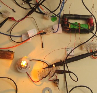
Here is my first attempt to replicate the opposing magnetic field interaction in a transformer.

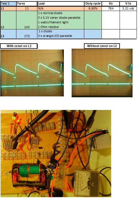
Cross area of the core: 176mm^2 ( 15mm Dia)

Description of coils: L1 15 turns 20 AWG right hand, L2 66 turns 22 AWG right hand, L3 70 turns 22 AWG right hand flip on core. Switching  L1 mosfet IRF 640  L2 diode 1N5408     L3 diode C82    

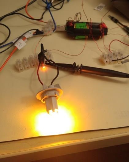
Load on L2: small 1 watts bulb (12V) and 4,8watts bulb Stanley 12V.    

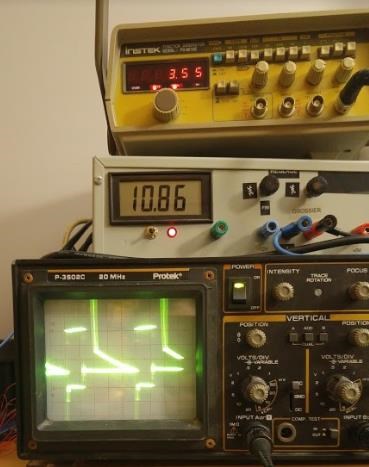
Signal generator frequency: 3.510Khz,  duty cycle of 23% (on time).

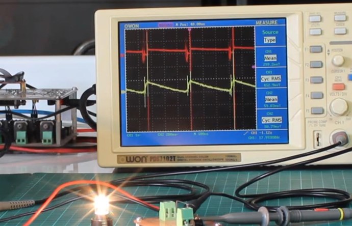
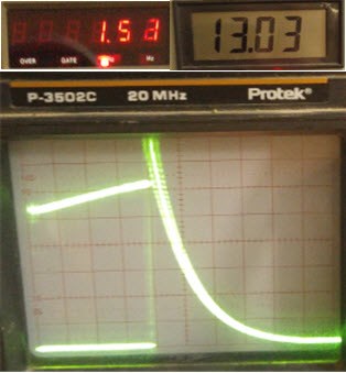
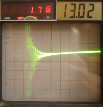
Oscilloscope: probe 1 (L1 input) 0,5Vdiv , input 2 (L2 parallel with load) 50mVdiv, 20uS time div.


My first impression is this:

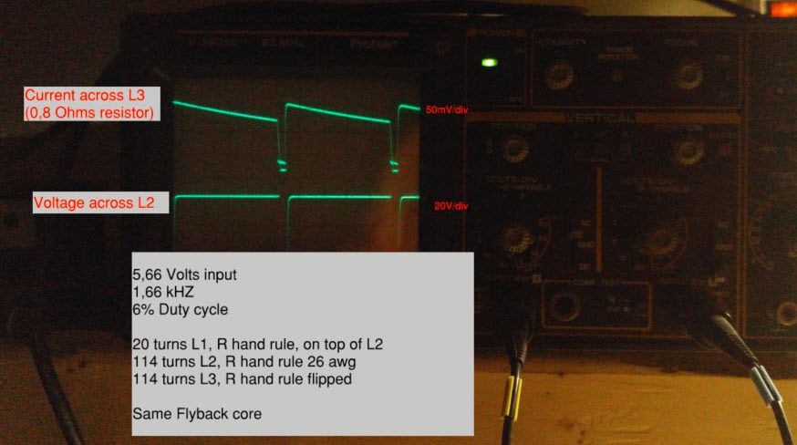
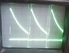
If I load more the L2 coil , the sawtooth is more apparent on the load input 2 scope.

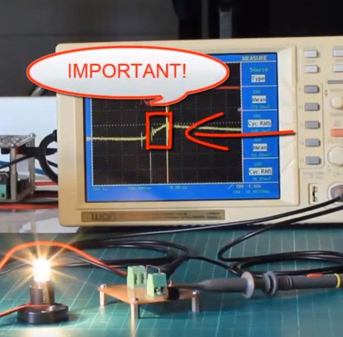
The negative spike wave is the charging of L1 is about 0,4 volts on the loads probe. The positive square wave is the input from the signal generator. After that there is a peak positive of 3,5 volts across output.

I think the charging of L1 is very fast.


Here is the circuit;


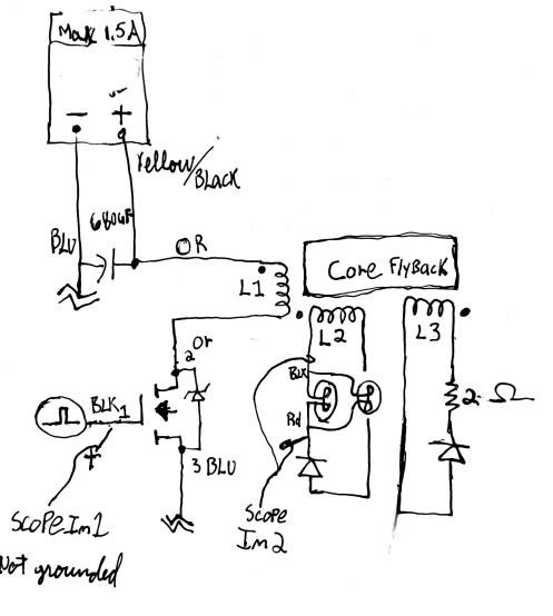
Any advice is appreciated 

Thx everyone!


Change is never easy but it's worth inertia.


''Change is never easy but it's worth inertia''

Order By: Standard | Newest | Votes
AETHERIC_MIND posted this 24 March 2022

Thx Melendor for you input on the caution with playing with wire under tension.

I've done new coils and upgraded the diode for 2 x R860D. The Diode are making a great difference at the scope trace (clearer)

Can you confirm with this image that the coils are slapping against each other?


PS: I'm not a beginner in electronics.


'' Change is never easy but it's worth inertia''

''Change is never easy but it's worth inertia''

Melendor posted this 11 December 2021

Hello AETHERIC MIND ,  and welcome back.

I am by no means an expert but I would love to point out some things from what I have experienced until now.

Because the Scope , is the device with which you are probing points of your circuit,it should  be grounded.
The power supply you can leave it floating , and if it is not floating , make it float.
(More than 1 ground / earth in a circuit = trouble )

** Check the thread  " Romanian ZPM " and see that after Fighter grounded the Scope and left the other devices floating , the traces on his scope became very clear. ~ NO Gound Loops any more

Now that you have a ground , place a 10k resistor at that Mosfet ,Gate to Ground.
The Mosfet must be 100% off when the Coils (L2 and L3) talk to each-other.

The Sawtooth wave , does not 100% mean that you got a working device.

The Sawtooth wave means , that the Current in the L2 coil can not Dissapear in an Instant (ns ) just because you Turned the Mosfet off.
The Current will have a linear decay until it is gone , and than ,you must hit the circuit with another pulse.

What @Cd_sharp stated above :

Hey, everyone That's current pumping during the off time. It's like we unplug our light bulb and it keeps lighting. Absolutely amazing! Thanks

is VALID if you got a working device !!! ( John , Cd.sharp , Chris , CaptainLoz etc )

If you do not have a working device , and you have like a 50-60% efficiency , the triangle wave shows you the linear decay of the Current that you HAVE placed in the device from the POWER supply ,  and not from the pumping of current because of the Bucking between L2 and L3.


If you want to make the transformer efficient ( L1 - L2 )  try to wind the turns as close to one another as you can.
L1 (Trigger ) should be on top of the L2 POC so that the efficiency of the transformer will be in the 80-95 % range.

!! Very important is the L2 Must Oppose L1 , 180* out of phase , and L3 must oppose L2 , 180* .

180* + 180* = 360* / In Phase. That means that the L3 if it opposes L2 coil , it must sustain L1 coil. He has no other way ,because the phase angle between them.

As Chris has said many times in his video , if you got a 50% efficient L1-L2 , you will never ever get above unity with so much power loss.


If I gap with my hand the core it vibrate alot.

Please do not touch the core or any of your circuit when it is on.
You safety comes first.

There is a reason Chris said , "" Start with 3 V and go higher only when you know the interactions ,and what is going on ""

When 2 waves hit one another there is a  pressure / Voltage between them. (like the 2 waves in the Ocean )
You can have 1000v - 2000v there , between those pressure points.

Welcome back , and I wish you lots of luck with the experiment.
Take care of yourself and your equipment !!

~~~Melendor the Wizard


AETHERIC_MIND posted this 11 December 2021

Hi every one,

I'm back on track. Here is the test with a normal diode and 3 x 5,1 volts zener diode on the L2 coil. I'm trying to create a delayed conduction. Probe #1 across 1 Ohm resistor on the L3 coil and probe #2 floating on the L1 only the positive is clip. We see the generation of voltage and current after the cutoff of the pulse. The interaction of L2 is during the upward of the current slope.If I put the zener on L2 there is more voltage and the integral of the trace cross the input duty cycle. 

Soon I will try a bigger E type core from an old inverter. 

''Change is never easy but it's worth inertia''

Chris posted this 05 March 2020

Awesome work AETHERIC_MIND!

You have joined the list of successful replications! Congratulations! You have achieved something many others have searched all their life to obtain! Congratulations on your achievement!

Now, a task of making Improvements. To increase the Potential, so more Power can be obtained for the same or less Input Power. Remember, Ohms Law: I = V / R, by Increasing I, allows for I to increase, and it costs you nothing more! Tricks, techniques we have been through before like: Delayed Conduction and so on can very easily increase your Potential.

You should be super proud of yourself!

Best wishes,

   Chris Sykes


AETHERIC_MIND posted this 05 March 2020


Here is a video of the Test 8.


''Change is never easy but it's worth inertia''

AETHERIC_MIND posted this 05 March 2020

Hi

Here is the test 8

I added a load on the L3 ( 4,8 watts bulb) and put the probe 1 across shunt wire in serie with the diode on L2.

Probe 2 across the load on L3 sawtooth wave form.


956 hz 8% duty cycle.

The scope shot talk by itself. Pretty amazing how the effect is amplified when I increase the voltage.

The scope shot was done at maybe 6 volts input.

If I gap with my hand the core it vibrate alot.

The position of the coils and the turn on L2 will be my next step forward in testing.


Thx everyone for following mey post


Change is never easy but it's worth inertia.


''Change is never easy but it's worth inertia''

Chris posted this 04 March 2020

Hey AETHERIC_MIND,

Great work! Thank You for sharing!

Your Waveform is not quite right. The ringing does not appear to have the right Magnetic Interactions there.

Each Coil has a job to do. Each Coil produces a series of Action Reaction Pairs.

The Actions are:

Action, Reaction and Counter-Reaction


So, the Input Coil Induces a Voltage on the Partnered Output Coil One, POne, POne then carry's a Current because it is Loaded. This is the Action, Input Coil, and the Reaction Secondary Coil.

The instant POne starts to Carry a Current, Partnered Output Coil Two, PTwo has an Induced Voltage because of this change in Current on POne, the Diode starts to Conduct and a Current Flows. This is the Counter-Reaction. The Current in PTwo must assist the Primary Current and also must Oppose POne.

This process occurs in this period:


During this period, the Coils have very little Impedance, because each Coil, this process occurs when the Coils Resonance point is found, and has the same effect as my experiment Reduced Impedance Effect.

Once this is done, we achieve a very hard Slapping together of the Magnetic Fields, we see a Voltage gained and Both Coils carry a Current. This is seen as a very slow Decay, a Sawtooth wave, because our Input is off, and the Partnered Output Coils now Pump Current for the remainder of the period:


Your'e getting close! Keep trying!

Your core might be a bit small, but stick with it for now and learn as much as you can!

Two videos to help:


Best wishes,

   Chris

AETHERIC_MIND posted this 04 March 2020

Hi

Here is an update

Test:7

I've tried to get the voltage higher on the bucking coil L3

I wind L3 with 145 turns and let the L2 at 70 turns. I added a diode D1 across the source drain 1n4007. I taked out the 2 ohm resistor on the L3 coil and put a shunt wire

The voltage across the load is bigger now.

The duty cycle is 8,5 % and the frequency is 1,52khz

Input voltage is 13,03 volts

Probe 1 on the gate leg( without ground cause i'm not isolated) and probe 2 across the load.

Time div 5us


Probe across load 5uS time div

I have the light bright but not a really good sawtooth wave on the load probe.

If I take the voltage across a shunt wire in serie with the load there is a ringing effect like a bouncing energy.

The wave form look like a damped LCR circuit but very fast.

This wave happen right after the input pulse and it's what is powering the load.

The time div is 1us

The same thing is seen on the shunt wire on the L3.


''Change is never easy but it's worth inertia''

Wistiti posted this 27 February 2020

Hey! great job!

Thanks for sharing and welcome abord!

Chris posted this 27 February 2020

Hey Aetheric_Mind,

Excellent work! Very nice to see your progress!

Bucking Coils, or Partnered output Coils work on the same basic principals as the Electric "Generator". One could say we are dealing with Solid State Electromagnetic Induction. I posted a post earlier on, here, that outlines this.

As you show, you have got a voltage and therefore a Current, this lights the Light, Power in the form of Watt seconds.

CSA, Coil Impedance, all the normal things must be taken into account, all these factors can under the right conditions increase the Output.

Voltage is one critical factor, if you can increase the Voltage on the Partnered Output Coils you will be able to increase your Output, Delayed Conduction is one method to achieve this.

Great work, excellent to see! Thank You for sharing!

Best wishes,

   Chris

We're Light Years Ahead!
Members Online:
What is a Scalar:

In physics, scalars are physical quantities that are unaffected by changes to a vector space basis. Scalars are often accompanied by units of measurement, as in "10 cm". Examples of scalar quantities are mass, distance, charge, volume, time, speed, and the magnitude of physical vectors in general.

You need to forget the Non-Sense that some spout with out knowing the actual Definition of the word Scalar! Some people talk absolute Bull Sh*t!

The pressure P in the formula P = pgh, pgh is a scalar that tells you the amount of this squashing force per unit area in a fluid.

A Scalar, having both direction and magnitude, can be anything! The Magnetic Field, a Charge moving, yet some Numb Nuts think it means Magic Science!

Message from God:

Hello my children. This is Yahweh, the one true Lord. You have found creation's secret. Now share it peacefully with the world.

Ref: Message from God written inside the Human Genome

God be in my head, and in my thinking.

God be in my eyes, and in my looking.

God be in my mouth, and in my speaking.

Oh, God be in my heart, and in my understanding.

Your Support:

More than anything else, your contributions to this forum are most important! We are trying to actively get all visitors involved, but we do only have a few main contributors, which are very much appreciated! If you would like to see more pages with more detailed experiments and answers, perhaps a contribution of another type maybe possible:

PayPal De-Platformed me!

They REFUSE to tell me why!

We now use Wise!

Donate
Use E-Mail: Chris at aboveunity.com

The content I am sharing is not only unique, but is changing the world as we know it! Please Support Us!

Thank You So Much!

Weeks High Earners:
The great Nikola Tesla:

Ere many generations pass, our machinery will be driven by a power obtainable at any point of the universe. This idea is not novel. Men have been led to it long ago by instinct or reason. It has been expressed in many ways, and in many places, in the history of old and new. We find it in the delightful myth of Antheus, who drives power from the earth; we find it among the subtle speculations of one of your splendid mathematicians, and in many hints and statements of thinkers of the present time. Throughout space there is energy. Is this energy static or kinetic? If static, our hopes are in vain; if kinetic - and this we know it is for certain - then it is a mere question of time when men will succeed in attaching their machinery to the very wheelwork of nature.

Experiments With Alternate Currents Of High Potential And High Frequency (February 1892).

Close